Rotation synchronization control method and system, computer equipment and storage medium
A technology of rotation synchronization and control method, which is applied in the field of computer equipment and storage media, systems, and rotation synchronization control method, which can solve problems such as low production speed, low degree of automation, and impact on production capacity, achieve high market promotion value, and improve the degree of automation and the effect on production speed
- Summary
- Abstract
- Description
- Claims
- Application Information
AI Technical Summary
Problems solved by technology
Method used
Image

Examples
Embodiment 1
[0053] In view of the defects existing in the prior art, the inventor actively researches and innovates on the basis of years of rich practical experience and professional knowledge in this industry, and cooperates with the application of theories, in order to create a practical and feasible rotation synchronous control technology to make it More practical. After continuous research, design and repeated trials and improvements, the present invention with real practical value is finally created.
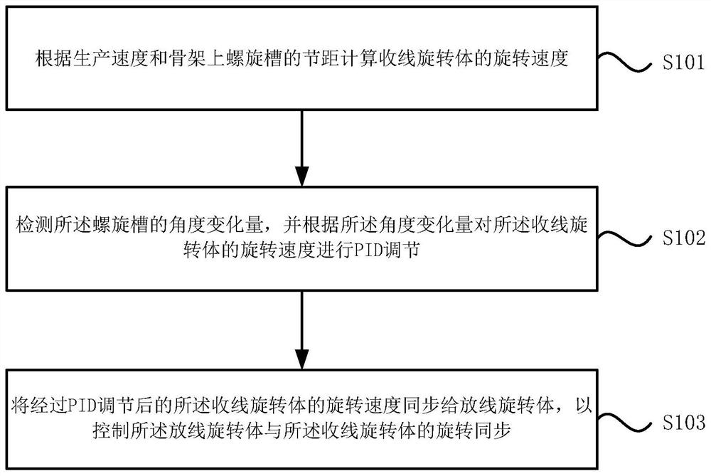
[0054] see figure 1 , figure 1 It is a schematic flow chart of a rotation synchronous control method disclosed in the embodiment of the present invention. This method is suitable for the scene of controlling the synchronous rotation of the take-up rotating body and the wire-releasing rotation during the production of skeleton optical cables. The method is executed by the rotation synchronous control system. The system can be realized by software and / or hardware, and is integrated insi...
Embodiment 2
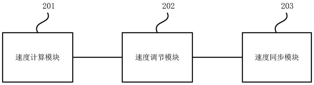
[0081] Please refer to the attached figure 2 , is a schematic diagram of functional modules of a rotation synchronization control system provided in Embodiment 2 of the present invention, and the system is suitable for implementing the rotation synchronization control method provided in the embodiment of the present invention. The system specifically includes the following modules:
[0082] The speed calculation module 201 is used to calculate the rotational speed of the take-up rotating body according to the production speed and the pitch of the spiral groove on the skeleton;
[0083] A speed adjustment module 202, configured to detect the angle change of the spiral groove, and perform PID adjustment on the rotation speed of the wire take-up rotating body according to the angle change;
[0084] The speed synchronization module 203 is used for synchronizing the rotation speed of the wire take-up rotating body adjusted by PID to the wire releasing rotating body, so as to cont...
Embodiment 3
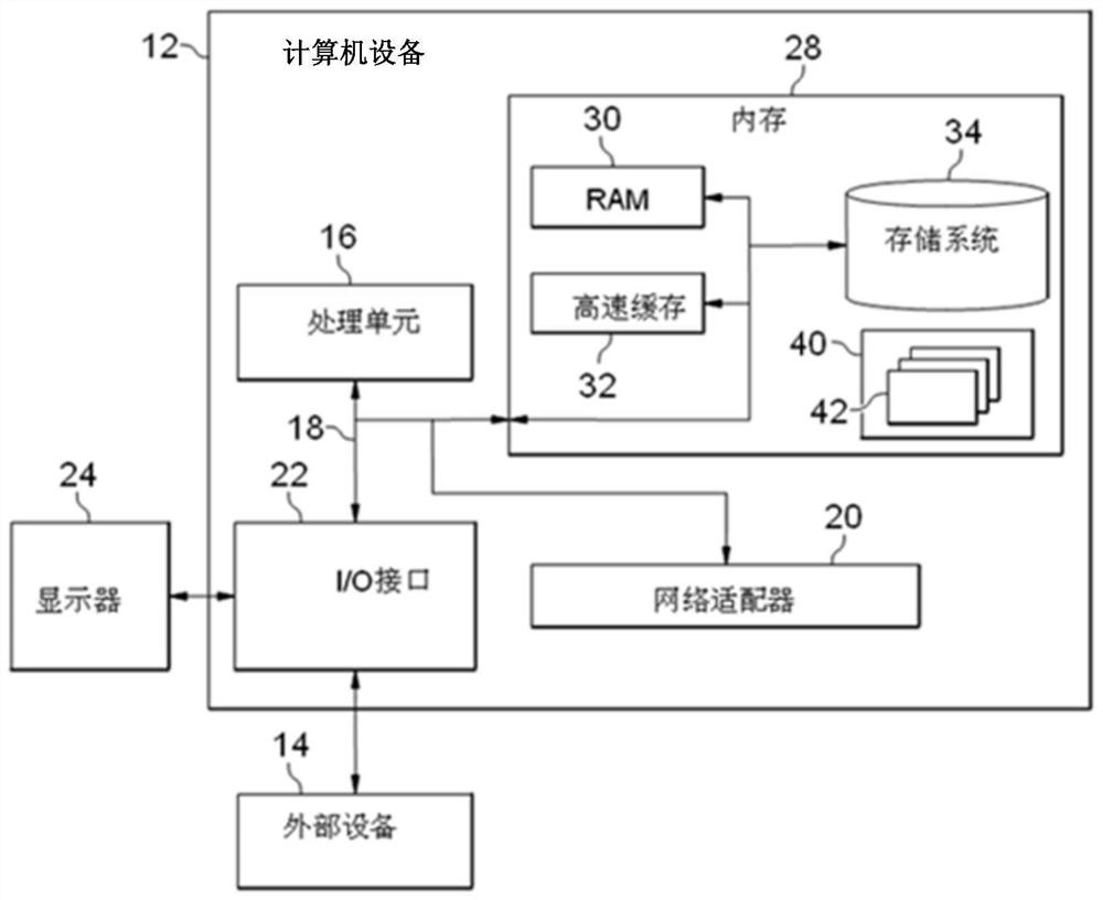
[0100] image 3 It is a schematic structural diagram of a computer device provided by Embodiment 3 of the present invention. image 3 A block diagram of an exemplary computer device 12 suitable for implementing embodiments of the invention is shown. image 3 The computer device 12 shown is only an example, and should not impose any limitation on the functions and scope of use of the embodiments of the present invention.
[0101] Such as image 3 As shown, computer device 12 takes the form of a general-purpose computing device. Components of computer device 12 may include, but are not limited to: one or more processors or processing units 16 , system memory 28 , bus 18 connecting various system components including system memory 28 and processing unit 16 .
[0102] Bus 18 represents one or more of several types of bus structures, including a memory bus or memory controller, a peripheral bus, an accelerated graphics port, a processor, or a local bus using any of a variety of ...
PUM
 Abstract
Description
Claims
Application Information
 - R&D
- Intellectual Property
- Life Sciences
- Materials
- Tech Scout
- Unparalleled Data Quality
- Higher Quality Content
- 60% Fewer Hallucinations
Browse by: Latest US Patents, China's latest patents, Technical Efficacy Thesaurus, Application Domain, Technology Topic, Popular Technical Reports.
© 2025 PatSnap. All rights reserved.Legal|Privacy policy|Modern Slavery Act Transparency Statement|Sitemap|About US| Contact US: help@patsnap.com