Heat management system

A heat management system and heat medium technology, applied in the field of heat management systems

Pending Publication Date: 2021-10-01
DENSO CORP
View PDF3 Cites 0 Cited by
  • Summary
  • Abstract
  • Description
  • Claims
  • Application Information

AI Technical Summary

Problems solved by technology

At this time, it is necessary to exchange heat between the cooling water in the cooling water circuit and the refrigerant of the heat pu

Method used


Image

  • Heat management system
  • Heat management system
  • Heat management system

Examples


no. 1 approach

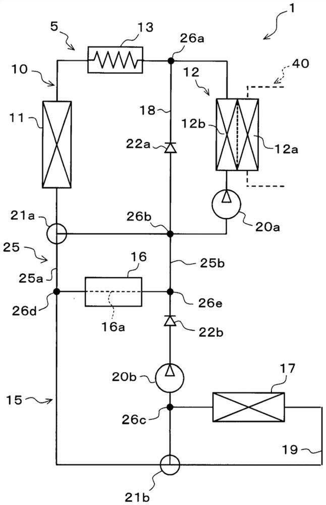
[0053] First, the schematic configuration of the thermal management system 1 according to the first embodiment will be described with reference to the drawings. The thermal management system 1 of the first embodiment is installed in an electric vehicle that obtains driving force for running from a motor generator.

[0054] The thermal management system 1 performs air conditioning of a vehicle interior as a space to be air-conditioned in an electric vehicle, and also performs temperature adjustment of an in-vehicle device (eg, heat generating device 16 ) as a temperature adjustment target. That is, the thermal management system 1 of the first embodiment is used as a vehicle air conditioner with a temperature adjustment function of an in-vehicle device in an electric vehicle.

[0055] In the thermal management system 1 in the first embodiment, the heat-generating device 16 that generates heat during operation is targeted for temperature adjustment. The heat generating device 16...

no. 2 approach

[0312] Next, refer to Figure 13 to Figure 23 , the thermal management system 1 of the second embodiment will be described. In the thermal management system 1 of the second embodiment, the configuration of the heat medium circuit 5 is changed from that of the first embodiment described above.

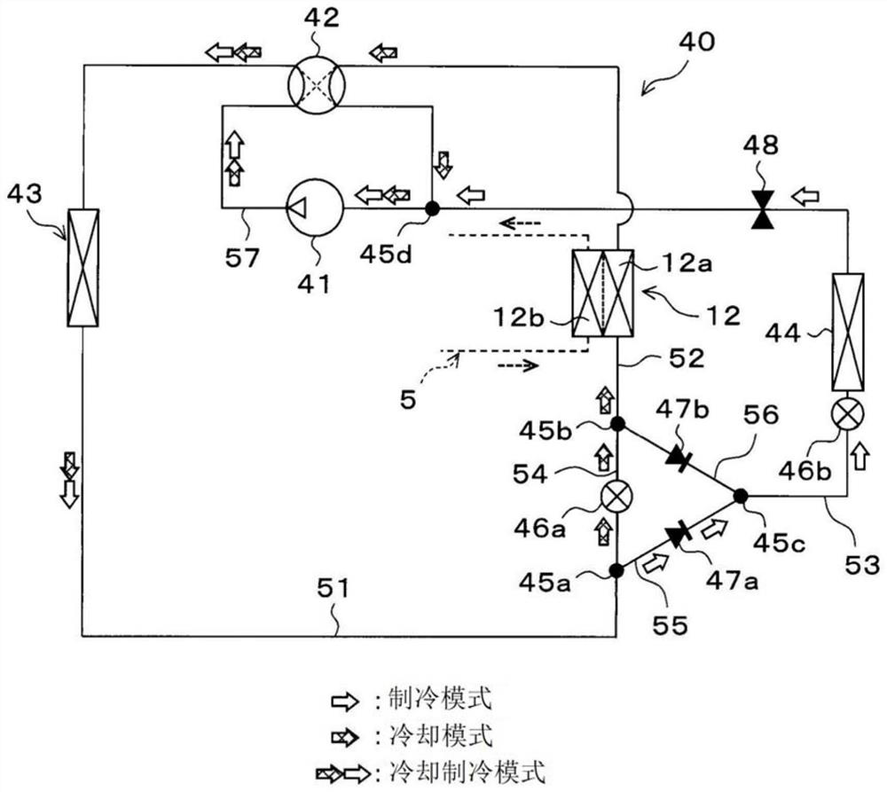
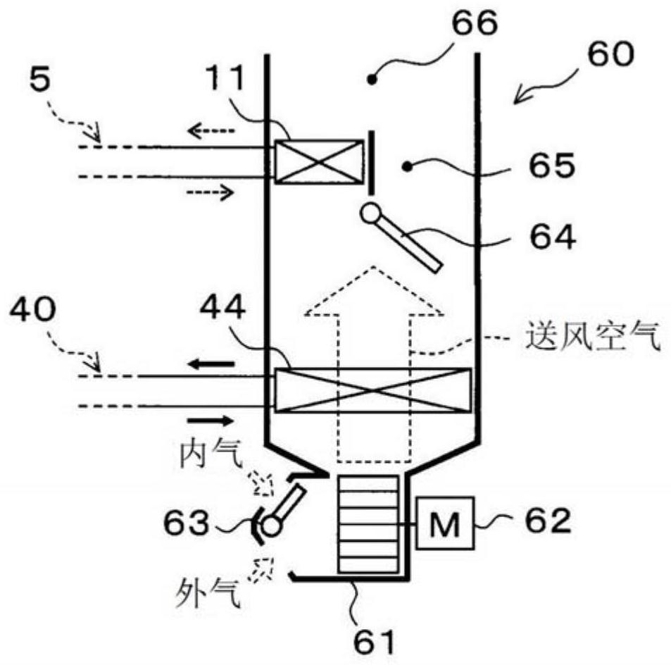
[0313] Therefore, in the thermal management system 1 of the second embodiment, the configurations of the refrigeration cycle 40, the indoor air-conditioning unit 60, and the control system of the control device 70 are the same as those of the first embodiment, and thus detailed description thereof will be omitted. In the following description of the second embodiment, differences from the first embodiment will be described.

[0314] Such as Figure 13 As shown, in the heat management system 1 of the second embodiment, the heat medium circuit 5 has: a battery 30 as a device to be adjusted in temperature, a third heat medium three-way valve 21c constituting a circuit switching unit, and...

no. 3 approach

[0540] Next, refer to Figure 24 , the thermal management system 1 of the third embodiment will be described. The thermal management system 1 of the third embodiment has the same basic structure as the thermal management system 1 of the second embodiment, and further includes a radiator on-off valve 28 .

[0541] Such as Figure 24 As shown, the radiator on-off valve 28 is disposed in the heat medium piping between the ninth connection portion 26 i and the heat medium inlet of the radiator 17 . The radiator on-off valve 28 opens and closes the heat medium passage between the ninth connection portion 26 i and the heat medium inlet of the radiator 17 , thereby switching whether or not the heat medium flows into and out of the radiator 17 .

[0542] The radiator on-off valve 28 is an electromagnetic valve whose operation is controlled by a control voltage output from the control device 70 . Therefore, in the third embodiment, the radiator on-off valve 28 constitutes a part of ...


PUM


Abstract

A heat management system (1) includes a high-temperature side heat medium circuit (10), a low-temperature side heat medium circuit (15), a circuit connecting unit (20), and a circuit switching unit (70c). The high-temperature side heat medium circuit (10) connects a heat medium/refrigerant heat exchanger (12) and a heater core (11) in such a way that a heat medium can circulate. The low-temperature side heat medium circuit (15) connects a radiator (17) and a heat generating appliance (16) in such a way that the heat medium can circulate. The circuit connecting unit (25) connects the high-temperature side heat medium circuit (10) and the low-temperature side heat medium circuit (15) in such a way that the heat medium can flow in an out. The heat management system (1) is switched by the circuit switching unit (70c) between an operating mode in which the heat medium heated by the heat medium/refrigerant heat exchanger (12) is circulated through the heater core (11), and an operating mode in which the heat medium heated by the heat generating appliance (16) and the heat medium refrigerant heat exchanger (12) is circulated through the heater core (11).

Description

[0001] Cross-reference of related applications [0002] This application is based on Japanese Patent Application No. 2019-35448 filed on February 28, 2019 and Japanese Patent Application No. 2020-22300 filed on February 13, 2020, the contents of which are cited here. technical field [0003] The present invention relates to a thermal management system suitable for a vehicle that obtains driving force for vehicle running from a running electric motor. Background technique [0004] Conventionally, as a technology applied to a thermal management system of an electric vehicle that obtains driving force for vehicle running from a running motor, for example, the technology of Patent Document 1 is known. In the vehicle heat pump air conditioner disclosed in Patent Document 1, the cooling water passing through the cooling water circuit recovers waste heat generated by a motor for driving the vehicle and a controller of the motor, and is used as a heat source for heating the vehicle ...

Claims


Application Information

Patent Timeline
IPC IPC(8): B60H1/22B60H1/08
CPCY02T10/70B60L50/64B60K11/02B60L58/26B60L58/27B60L2240/545B60L1/02B60H1/00278B60H2001/00307B60H1/00885B60H1/32281B60K2001/005H01M10/625H01M10/617H01M10/633H01M10/6568H01M10/663Y02E60/10
Inventor 福井康晃梯伸治早濑友宏
Owner DENSO CORP
Why Eureka
Try Eureka