Integrated laser damage surface observation system

An observation system, laser damage technology, applied in the direction of optical testing flaws/defects, measuring devices, material analysis through optical means, etc., to achieve the effect of improving focusing imaging ability and resolution, simple device structure, and wide application range

Inactive Publication Date: 2021-10-08
NANKAI UNIV
View PDF21 Cites 0 Cited by
  • Summary
  • Abstract
  • Description
  • Claims
  • Application Information

AI Technical Summary

Problems solved by technology

[0009] In order to solve the above-mentioned defects in the existing laser-damaged sample surface observation system, the present invention provides an integrated laser-damaged surface observation system, and provides a test flow for observing the damaged surface

Method used


Image

  • Integrated laser damage surface observation system
  • Integrated laser damage surface observation system
  • Integrated laser damage surface observation system

Examples


Embodiment 1

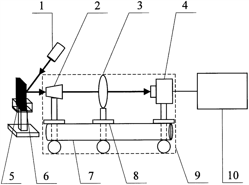
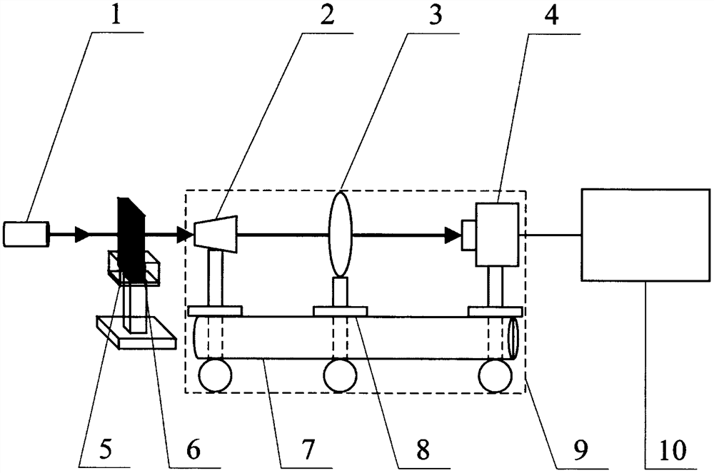
[0032] like figure 1 As shown, an integrated laser damage surface observation system, including: LED light source-1, microscope objective lens-2, tube lens-3, CCD camera-4, clamping device-5, silicon wafer damaged by laser- 6. Lifting column-7, gear slide-8, coaxial system-9, computer-10.

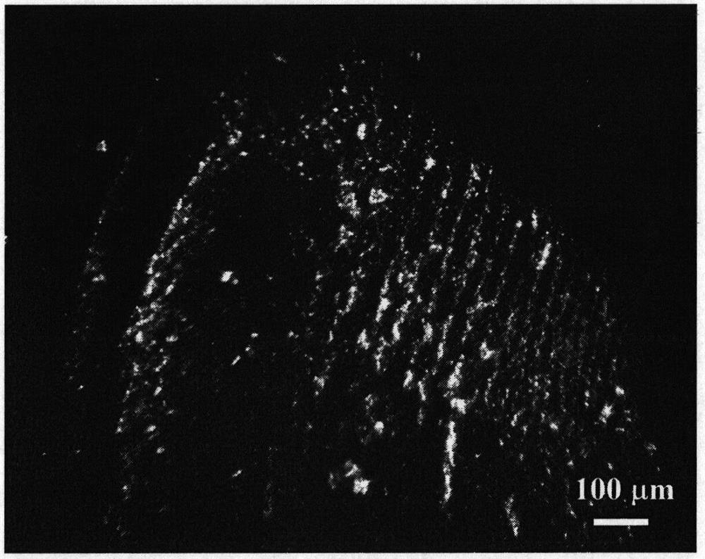
[0033] Among them: the silicon wafer damaged by the laser-6 is fixed by the clamping device-5, the observation illumination light source is emitted from the LED light source-1, and enters the microscope objective lens-2 after being reflected by the surface of the silicon wafer; the microscope objective lens-2, tubular The lens-3 and the CCD camera-4 form a microscopic observation system, which is placed on the coaxial system-9 to ensure that the incident light is coaxial. The coaxial system-9 is composed of a lifting cylinder-7 and a gear slide-8, and can be horizontal or vertical Move straight; the damaged surface of the silicon wafer is imaged by the CCD camera-4 of the microscopic obser...


PUM


Abstract

The invention relates to an integrated laser damage surface observation system which is characterized in that after being illuminated by an LED light source, a sample damaged surface is amplified and imaged by a microscope objective, a tubular lens and a CCD camera on a coaxial system, and is displayed in a computer in real time for image processing. Reflection-type observation can be adopted for light-proof samples, transmission-type observation can be adopted for light-transmitting samples, and the microscope objective, the tubular lens and the CCD camera are integrated through the coaxial system, so that it is guaranteed that incident light rays are coaxial; the coaxial system can be moved for focusing, so that aberration can be effectively reduced, and a light path can be adjusted conveniently. The system is simple in device and structure, is in self-assembly design, has adjustable magnification times and low cost, can measure the damage degree from the surface fine structure change level, and can be applied to the technical fields of laser damage, laser damage and the like.

Description

technical field [0001] The invention relates to the technical field of laser damage, in particular to an integrated laser damage surface observation system. Background technique [0002] With the development of laser technology, the damage effect and evaluation technology of high-energy laser has become an important part of modern science and technology and modern weapons. It is very important to effectively observe the damaged surface of samples after high-energy laser radiation and evaluate different damage degrees. significance. [0003] However, the following problems exist in the existing laser damage sample surface observation system: [0004] (1) The LED light source of a small optical microscope is mostly installed directly above the sample stage, and can only be observed by transmission, testing samples that can transmit light, and samples that are opaque cannot be observed; [0005] (2) The experimental device of the reflection microscope is relatively large and ...

Claims


Application Information

Patent Timeline
Patent Type & Authority Applications(China)
IPC IPC(8): G01N21/88
CPCG01N21/8851G01N2021/8887
Inventor 匡登峰刘刚铄徐灿
Owner NANKAI UNIV
Why Eureka
Try Eureka