Eureka AIR delivers breakthrough ideas for toughest innovation challenges, trusted by R&D personnel around the world.

Direct-current droplet generator and preparation method thereof

A generator and droplet technology, applied in the field of power generation technology and sensing, can solve the problems of reducing portability and stability, increasing costs, increasing additional circuit energy loss, etc., to improve water energy utilization, stable output, The effect of output performance improvement

Active Publication Date: 2021-10-08
SOUTHWEST UNIVERSITY
View PDF10 Cites 2 Cited by
  • Summary
  • Abstract
  • Description
  • Claims
  • Application Information

AI Technical Summary

Problems solved by technology

The introduction of power management circuits will inevitably increase the complexity of the water energy harvesting system, which will not only increase additional circuit energy loss, reduce portability and stability, but also greatly increase the cost
Therefore, the current water energy harvesting power generation system still has a very big challenge to the actual application.

Method used


Image

  • Direct-current droplet generator and preparation method thereof
  • Direct-current droplet generator and preparation method thereof
  • Direct-current droplet generator and preparation method thereof

Examples


Embodiment 1

[0029] The present invention will be described in further detail below with the preparation of DC droplet generator, and this method comprises the steps:

[0030] Step 1: Construction of Solid Hydrophobic Surface

[0031] Select a commercially processed PTFE plate as the material for the required solid surface (11), because the PTFE surface has contact charging characteristics after friction with the droplet, and no pre-charging is required; because the PTFE surface is hydrophobic, no additional treatment is required. Ultrasonic cleaning with acetone for 10 minutes each, then drying at 100°C for later use;

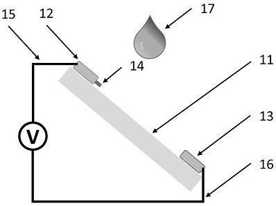
[0032] Step 2: Arranging Electrodes and Assembling the Droplet Generator

[0033] The upper electrode (12) and the lower electrode (13) use copper sheet, aluminum sheet or titanium sheet as the conductive electrode, and a conductive copper wire, titanium wire or platinum wire is attached as the collector needle (14), and the lower electrode (13) In this embodiment, no co...

Embodiment 2

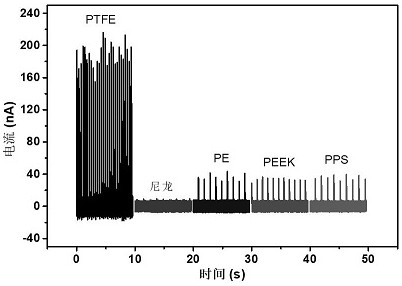
[0038] In order to demonstrate the power generation effect of the DC droplet generator of the present invention, the solid surface 11 of the present invention is a hydrophobic surface of any artificial or natural material, and the following non-limiting examples are used for further detailed description: using PTFE, Nylon, PE, Six materials of PEEK, POM, and PPS were used to manufacture the DC droplet generator of the invention, and the current output performance of the DC droplet generator based on different materials was tested respectively ( image 3 ), further confirming the versatility of the device of the present invention.

Embodiment 3

[0040] The DC droplet generator of the present invention has dual working modes of DC and AC.

[0041] The DC droplet generator of the present invention not only has a kind of DC working mode as mentioned above, but also has another working mode; refer to Figure 4 , when the droplet is in contact with both the collector needle 14 and the lower electrode 13, the output current of the DC droplet generator is DC; when the droplet drop position is adjusted so that the droplet does not touch the collector needle 14 and the upper electrode 12, when only contacting the lower electrode 13, under the condition of keeping other conditions unchanged, the output current of the DC droplet generator becomes AC, which shows that the DC droplet generator of the present invention has dual operation of DC and AC model.


PUM

PropertyMeasurementUnit
sizeaaaaaaaaaa

Abstract

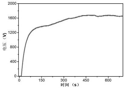
The invention discloses a direct-current droplet generator and a preparation method thereof. The generator is characterized in that the generator has a structure in which all electrodes are placed above a solid surface and do not need to be grounded, so that the direct-current liquid drop generator can be constructed on any surface including a block body, a thin film and a coating; the droplet generator structure comprises a solid hydrophobic surface, an upper electrode, a collector pin, a lower electrode, an upper electrode lead and a lower electrode lead. The solid surface is a hydrophobic surface made of any artificial or natural materials, the upper electrode and the lower electrode are placed on the solid surface at a certain interval, the current collecting needle can be of an independent conductive tip structure and can also be directly machined on the electrode, and the generator can collect electric energy by impacting the surface through liquid drops. Compared with the prior art, the direct-current droplet generator can be constructed on any solid surface, the collected liquid mechanical energy is converted into the electric energy with the direct-current characteristic, and the direct-current droplet generator has the advantages of being simple in preparation process and low in cost. The open-circuit voltage of the direct-current liquid drop generator is up to kilovolt, a power management circuit is not needed, and the direct-current liquid drop generator can directly drive micro electronic devices to work or charge an energy storage unit. The structure of the direct-current generator has the functions of power generation, rectification and energy storage at the same time, a new technology based on solid-liquid interface water energy collection is developed, and the practical progress of water energy collection is greatly accelerated; meanwhile, the device is also a sensor or a probe. Due to the fact that the device achieves effective separation of charges, the device has extremely high application value in the aspects of droplet energy collection and self-driven sensing.

Description

technical field [0001] The invention relates to the field of power generation technology and sensing, in particular to a universal power generation technology and power generation device based on a solid-liquid interface. Background technique [0002] Energy provides an inexhaustible source of power for the development of human society, and converting other forms of energy into efficient and controllable electrical energy is one of the important directions for the development of the energy field. The current power generation technology is still dominated by traditional fossil energy, which has brought about problems of climate change and environmental pollution that cannot be ignored. New energy technologies have arisen at the historic moment and have been vigorously developed. At present, they mainly include water energy, nuclear energy, solar energy, wind energy and other technologies, which have broad application prospects. Among them, water covers 71% of the earth's sur...

Claims


Application Information

Patent Timeline
Patent Type & Authority Applications(China)
IPC IPC(8): H02J7/32H02J7/34H02N1/04H02K44/08H02K44/10
CPCH02J7/32H02J7/345H02N1/04H02K44/085H02K44/10
Inventor 宋群梁董君朱丽丽
Owner SOUTHWEST UNIVERSITY
Why Eureka
Eureka Blog
Learn More