Constructed wetland system and method for heat preservation in winter by recycling geothermal energy

A kind of artificial wetland system and artificial wetland technology, applied in the field of sewage treatment, can solve the problems of high cost, low pollutant removal rate, only 25%, 35%, etc., achieve low cost, high pollutant removal rate, and ensure groundwater balance Effect

Pending Publication Date: 2021-10-22
UNIV OF JINAN
View PDF6 Cites 0 Cited by
  • Summary
  • Abstract
  • Description
  • Claims
  • Application Information

AI Technical Summary

Problems solved by technology

The icing method is to add ice, straw and other isolation layers on the surface of the subsurface wetland to prevent the artificial wetland from freezing, but the removal rates of TN and TP in the wetland are only 25% and 35% respectively; the mulching method is to cover the surface of the wetland with mulch. Effectively improve the removal efficiency of ammonia nitrogen in wetlands, but the removal rate of COD, TN, NH4+-N is not high
The pig manure and reed composting method cannot be applied to large-scale wetlands because the survival life of wetlands is about 40 days
The straw mulching method is to use harvested plants to cover the constructed wetlands to keep warm under the low temperature conditions in winter, but the removal rates of TP, NH4+-N, and TN are only 31.4%, 26.5%, and 9.6%, which are lower than those of the constructed wetlands that are not covered with plants. The effect is only increased by 15.5%, 9.7%, 5.0% respectively
[0005] I

Method used


Image

  • Constructed wetland system and method for heat preservation in winter by recycling geothermal energy
  • Constructed wetland system and method for heat preservation in winter by recycling geothermal energy
  • Constructed wetland system and method for heat preservation in winter by recycling geothermal energy

Examples


Embodiment Construction

[0031] Below in conjunction with accompanying drawing and embodiment the present invention will be further described:

[0032] In order to clearly illustrate the technical features of this solution, the present invention will be described in detail below through specific implementation modes and in conjunction with the accompanying drawings. The following disclosure provides many different embodiments or examples for implementing different structures of the present invention. To simplify the disclosure of the present invention, components and arrangements of specific examples are described below. Furthermore, the present invention may repeat reference numerals and / or letters in different instances. This repetition is for the purpose of simplicity and clarity and does not in itself indicate a relationship between the various embodiments and / or arrangements discussed. It should be noted that components illustrated in the figures are not necessarily drawn to scale. Description...


PUM


Abstract

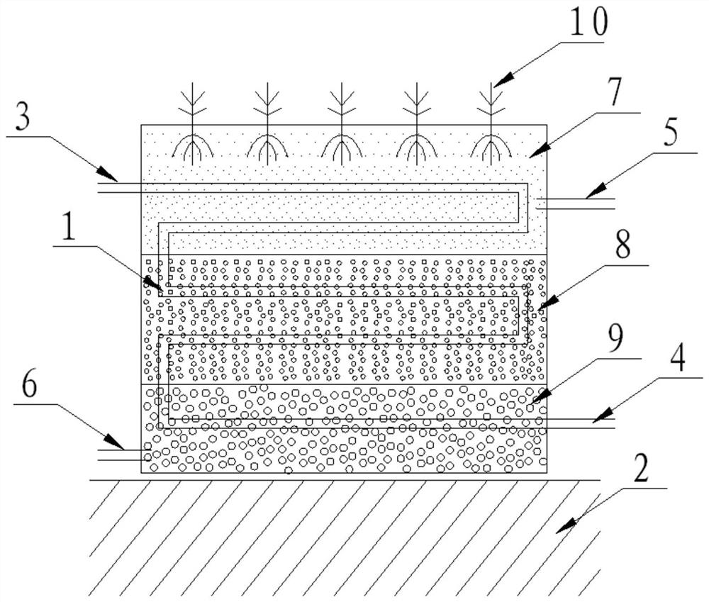
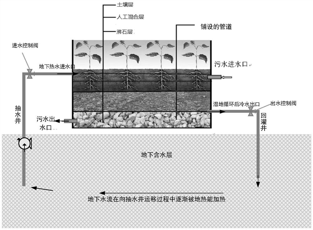
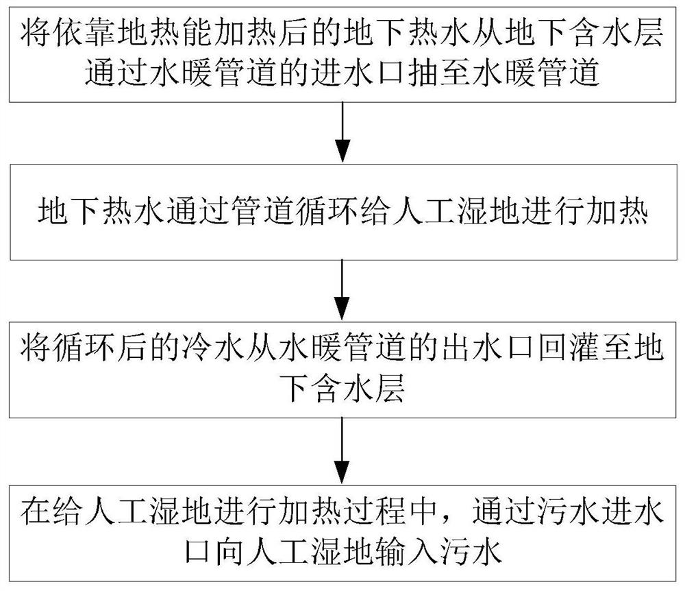
The invention discloses an artificial wetland system and method for heat preservation in winter by recycling geothermal energy, an artificial wetland comprises a wetland substrate, a sewage inlet, a sewage outlet, a water heating pipeline and an underground aquifer, the water heating pipeline is laid in the wetland substrate, a water inlet of the water heating pipeline is located at the upper part of the wetland substrate, a water outlet of the water heating pipeline is positioned at the lower part of the wetland substrate; the sewage inlet and the sewage outlet are respectively formed in the upper part and the lower part of the wetland substrate; the wetland substrate at least comprises a soil layer, an artificial mixing layer and a zeolite layer, wetland plants are planted on the soil layer, a first water heating pipeline, a second water heating pipeline and a third water heating pipeline which are connected end to end are arranged in the soil layer, the artificial mixing layer and the zeolite layer respectively, underground hot water is inputted into the water inlet of the first water heating pipeline, and the water outlet of the third water heating pipeline inputs cold water into the underground aquifer. According to the invention, a higher temperature in the wetland in winter can be ensured, so that a higher pollutant removal rate is achieved.

Description

technical field [0001] The invention relates to an artificial wetland system and method for recycling geothermal energy to keep warm in winter, and belongs to the technical field of sewage treatment. Background technique [0002] Constructed wetlands have broad application prospects in such areas because of their low cost and easy maintenance. Up to now, constructed wetland has been proved to be an economical and effective means of domestic sewage treatment, and has been widely used at home and abroad, and has achieved relatively ideal results, becoming one of the mainstream processes of domestic sewage treatment. [0003] The constructed wetland system is a sewage treatment system that simulates the natural wetland ecosystem, and mainly relies on a series of reactions such as physics, chemistry, biology, and microorganisms to achieve the purpose of sewage purification. In the cold northern regions, when the temperature drops below zero in winter, the water surface will fre...

Claims


Application Information

Patent Timeline
IPC IPC(8): C02F3/32
CPCC02F3/32
Inventor 韩延成王月蕾周欣悦方攀博陈思涵黄兆虎王栋
Owner UNIV OF JINAN
Why Eureka
Try Eureka