System and method for continuously and flexibly preparing methane by utilizing renewable energy sources

A renewable energy and energy storage system technology, applied in the direction of electric energy storage system, energy storage, energy input, etc., can solve the problems of inability to realize thermal integration of devices, increase the scale of process equipment, limit economic feasibility, etc., and achieve thermal Integrate and heat cycle, avoid volatility and intermittency, and improve the effect of energy utilization efficiency

Pending Publication Date: 2021-10-22
CHINA UNIV OF PETROLEUM (EAST CHINA)
View PDF0 Cites 0 Cited by
  • Summary
  • Abstract
  • Description
  • Claims
  • Application Information

AI Technical Summary

Problems solved by technology

[0002] At present, many countries in the world have built demonstration devices for renewable energy gas production or liquid fuels, but the large-scale promotion of renewable energy gas production or liquid fuel devices still faces a series of problems. For the traditional renewable energy methane production process (Including electrolyzed water hydrogen production unit and methanation unit) cannot provide continuous and flexible operation, leading to the key technical bottleneck of high cost and high energy consumption, which has great limitations in the implementation in industry, mainly There are the following points:
[0003] (1) Due to the inability to deal with the intermittency of renewable energy, the efficiency of energy utilization is low; at the same time, the fluctuation of device production makes it impossible to perform high-temperature operation of water electrolysis and apply the latest high-efficiency electrolyzer equipment, that is, solid oxide electrolysis equipment; in addition, electrolysis Inconsistent operation between units and methanation units does not enable heat integration between units, resulting in lower energy efficiency and higher energy consumption for methane production;
[0004] (2) The traditional process realizes the production of methanation reactor by storing a large amount of hydrogen, and hydrogen storage is often high-pressure storage; Can cause safety hazards and increase production costs
In addition, the frequent start-up and shutdown of various components of the production device due to the fluctuation of renewable energy will also lead to potential operating costs and safety risks;
[0005] (3) This traditional process cannot support production planning and scheduling to consider the real-time needs of the power grid and pipe network side; the actual grid side has a large number of photovoltaic and wind power curtailment, and this part of low-cost curtailment cannot be effectively utilized, resulting in energy waste
However, most of the current liquid carbon dioxide energy storage systems are only applied to individual power grid peak regulation and power energy storage, and no one has proposed that it can be coupled with renewable energy methane production processes to break through the above key technical bottlenecks
[0007] In addition, the existing liquid carbon dioxide energy storage system mainly has the following limitations: (1) It is necessary to compress carbon dioxide from a low-pressure storage tank to a high-pressure storage tank for energy storage; Carbon dioxide storage tanks are not yet feasible; (2) multiple heat storage cycles are required to achieve adiabatic operation of the energy storage system, and a series of heat storage cycles require additional working fluids (such as methanol) and additional process equipment and storage facilities; this increases the complexity of process operations and power storage costs; (3) the system has a lower energy storage density (3 ), the low energy storage density will not only increase the size of the process equipment, but also further limit the economic feasibility of the implementation of the system

Method used


Image

  • System and method for continuously and flexibly preparing methane by utilizing renewable energy sources
  • System and method for continuously and flexibly preparing methane by utilizing renewable energy sources
  • System and method for continuously and flexibly preparing methane by utilizing renewable energy sources

Examples


Embodiment Construction

[0056] In order to make the advantages and technical solutions of the present invention clearer and clearer, the present invention will be described in detail below in conjunction with specific embodiments and accompanying drawings.

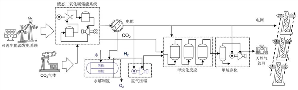
[0057] refer to figure 1 , the present invention provides a continuous and flexible system for producing methane from renewable energy sources, including renewable energy power generation systems, liquid CO 2 Energy storage system, methanation production system, the renewable energy power generation system and liquid CO 2 The energy storage system is connected and is liquid CO 2 The energy storage system provides electrical energy, the liquid CO 2 The energy storage system is connected to the methanation production system and provides CO for the methanation reaction 2 , the electrical energy required by the methanation production system consists of liquid CO 2 Energy storage system or grid power supply.

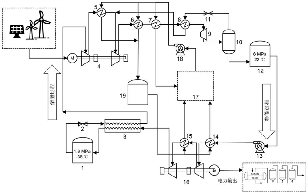
[0058] refer to figure 2 , the liq...


PUM


Abstract

The invention discloses a system and method for continuously and flexibly preparing methane through renewable energy sources. The system comprises a renewable energy power generation system, a liquid CO2 energy storage system and a methanation production system, wherein the renewable energy power generation system is connected with the liquid CO2 energy storage system and provides electric energy for the liquid CO2 energy storage system; the liquid CO2 energy storage system is connected with the methanation production system and provides CO2 for a methanation reaction; and electric energy required by the methanation production system is provided by the liquid CO2 energy storage system or power of a power grid. According to the system for preparing methane from renewable energy, the liquid CO2 energy storage system is coupled with the renewable energy power generation system, power is supplied to the methanation production system through the liquid CO2 energy storage system, stable and continuous power output can be provided for the methanation production system, fluctuation and intermittency of the renewable energy are avoided, stable and continuous operation of the methanation production system is realized, and power peak regulation of the power grid is also supported.

Description

technical field [0001] The invention relates to the technical fields of renewable energy utilization, carbon emission reduction and resource utilization, in particular to a system and method for continuously and flexibly utilizing renewable energy to prepare methane. Background technique [0002] At present, many countries in the world have built demonstration devices for renewable energy gas production or liquid fuels, but the large-scale promotion of renewable energy gas production or liquid fuel devices still faces a series of problems. For the traditional renewable energy methane production process (Including electrolyzed water hydrogen production unit and methanation unit) cannot provide continuous and flexible operation, leading to the key technical bottleneck of high cost and high energy consumption, which has great limitations in the implementation in industry, mainly There are the following points: [0003] (1) Due to the inability to deal with the intermittency of...

Claims


Application Information

Patent Timeline
IPC IPC(8): C10L3/08H02J3/28H02J3/38H02J3/00H02J15/00C07C1/12C07C9/04C25B1/04C25B9/67C25B15/021
CPCC10L3/08H02J3/28H02J3/381H02J3/008H02J15/00H02J15/006C07C1/12C25B1/04C25B9/67C25B15/021C07C9/04Y02E60/36Y02E70/30Y02P20/133
Inventor 戚萌刘义
Owner CHINA UNIV OF PETROLEUM (EAST CHINA)
Why Eureka
Try Eureka