Supercharge Your Innovation With Domain-Expert AI Agents!

Low-speed direct-drive motor disturbance suppression method based on sliding mode and disturbance compensation

A technology of disturbance compensation and disturbance suppression, applied in motor generator control, motor control, AC motor control, etc., can solve the problem that the low frequency time-varying torque disturbance suppression effect is not obvious, so as to improve the disturbance suppression ability and reduce the complexity. , the effect of the simple structure of the observer

Pending Publication Date: 2021-10-26
NANJING UNIV OF AERONAUTICS & ASTRONAUTICS
View PDF2 Cites 3 Cited by
  • Summary
  • Abstract
  • Description
  • Claims
  • Application Information

AI Technical Summary

Problems solved by technology

[0004] Aiming at the deficiencies of the above-mentioned prior art, the main technical problem to be solved by the present invention is that the control rate and observer design of the existing sliding mode method are complicated, and the low-frequency time-varying torque disturbance suppression effect is not obvious during low-speed operation, and a new method is proposed. A torque disturbance suppression method for low-speed direct-drive motors based on sliding mode and disturbance compensation, which has the advantages of being able to suppress the influence of low-frequency disturbances, without providing disturbance information, and having a simple structure design. Simultaneously suppress low-frequency and medium-high frequency torque ripple at extremely low speeds, improving the control accuracy of direct drive servo motors at low speeds

Method used


Image

  • Low-speed direct-drive motor disturbance suppression method based on sliding mode and disturbance compensation
  • Low-speed direct-drive motor disturbance suppression method based on sliding mode and disturbance compensation
  • Low-speed direct-drive motor disturbance suppression method based on sliding mode and disturbance compensation

Examples


Embodiment Construction

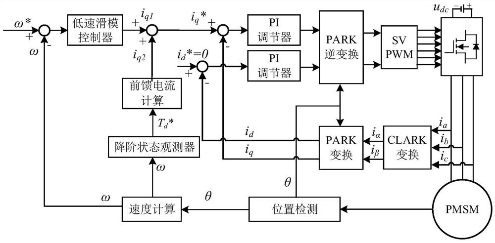
[0071] Further detailed description of the technical solutions of the present invention will be described below with reference to the drawings:

[0072] (1) collecting a three-phase current information, coordinate transformation, to establish vector control mathematical model of the permanent magnet synchronous motor (PMSM) dq coordinate system;

[0073]

[0074] Where, ω is the mechanical angular velocity, p n Number of pole pairs, u d U q Is d and q-axis armature voltage component, i d I q Corresponds to the armature current component, R s The armature resistance, ψ f The motor rotor flux, L d L q Motor direct and quadrature axis inductance.

[0075] In particular, for a surface mounted permanent magnet synchronous motor L d = L q , Its torque equation is:

[0076]

[0077] Mechanical equations of motion are:

[0078]

[0079] Among them, T e A permanent magnet synchronous motor electromagnetic torque, J is the moment of inertia, T L Is the load torque, B a For the damping...


PUM


Abstract

The invention discloses a low-speed direct-drive motor disturbance suppression method based on a sliding mode and disturbance compensation. The method is applied to the technical field of direct-drive servo of aerospace, robots, numerical control machine tools and the like. Aiming at the defects that the sliding mode controller is complex in design and the time-varying disturbance suppression effect is not obvious during low-speed operation, a mode of combining the low-speed sliding mode controller and the reduced-order state observer time-varying disturbance compensation is adopted, the system structure complexity is reduced, and the disturbance suppression effect during low-speed operation of the motor is improved. According to the method, the influence of low-frequency disturbance is mainly inhibited by the sliding mode controller, disturbance information does not need to be provided, the structural design is simple, load disturbance feed-forward compensation is added, the motor can be driven to simultaneously inhibit low-frequency and medium-high-frequency torque pulsation at an extremely low rotating speed, and the control precision of the direct-drive servo motor during low-speed operation is improved.

Description

Technical field [0001] The present invention relates to the field of motor control, and particularly to a sliding mode disturbance compensation based on the low-speed direct drive motor disturbance suppression method. Background technique [0002] Direct-drive permanent magnet synchronous motor servo system in recent years, widely used in aerospace, CNC machine tools and other high-performance, high-precision control applications. Direct drive system does not use a reduction gear mechanism, a servo motor connected to the load, and there is no backlash motion transmission lag to achieve higher accuracy, efficiency and responsiveness. But the same face many problems: such as motor cogging, load changes, higher current harmonics and other disturbances mechanical friction, since no intermediate links of the reducer, acting directly on the motor shaft, affect the running accuracy of the speed control system stability and, at the same time, the influence of the disturbance torque, whil...

Claims


Application Information

Patent Timeline
IPC IPC(8): H02P21/00H02P21/13H02P6/34H02P25/026H02P27/08
CPCH02P21/0007H02P21/13H02P6/34H02P25/026H02P27/08H02P2207/05
Inventor 卜飞飞李晨曦郭子韬郭润泽李星兆
Owner NANJING UNIV OF AERONAUTICS & ASTRONAUTICS
Features
  • R&D
  • Intellectual Property
  • Life Sciences
  • Materials
  • Tech Scout
  • Unparalleled Data Quality
  • Higher Quality Content
  • 60% Fewer Hallucinations
Learn More