
Medium-high speed ship diesel engine cylinder cover machining device

A marine diesel engine and processing device technology, applied in metal processing equipment, metal processing machinery parts, manufacturing tools, etc., can solve the problems of intricate piping system, high cost, inconvenient use, etc., and achieve simple and fast operation, fast and convenient operation, and guaranteed Effect of connection strength and tightness

Pending Publication Date: 2021-10-29
ANQING CSSC MATING POWER
View PDF4 Cites 0 Cited by
  • Summary
  • Abstract
  • Description
  • Claims
  • Application Information

AI Technical Summary

Problems solved by technology

[0004] It can be seen that the production line needs to be equipped with at least two cutting fluid treatment systems and piping systems connected to the cutting fluid processing systems, which leads to intricate piping systems and high costs.
[0005] In addition, it is necessary to plan the production line in advance before the layout of the pipeline system to ensure that the installation position of the machine tool in the production line corresponds to the corresponding pipe joint, that is, each machine tool needs to be connected to the cutting fluid treatment system corresponding to the cutting fluid it uses, so that the position of the machine tool cannot be changed. , the production line cannot be adjusted, not suitable for flexible processing
[0006] And if multiple pipe joints are installed on each machine tool installation station to connect different cutting fluid treatment systems, the required pipe joints can be selectively connected when connecting, but the wrong pipe system may also be connected when connecting , very inconvenient to use

Method used


Image

  • Medium-high speed ship diesel engine cylinder cover machining device
  • Medium-high speed ship diesel engine cylinder cover machining device
  • Medium-high speed ship diesel engine cylinder cover machining device

Examples


Embodiment 1

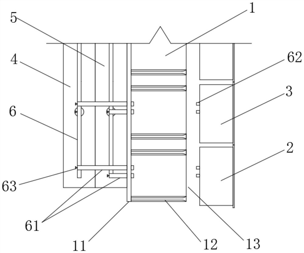
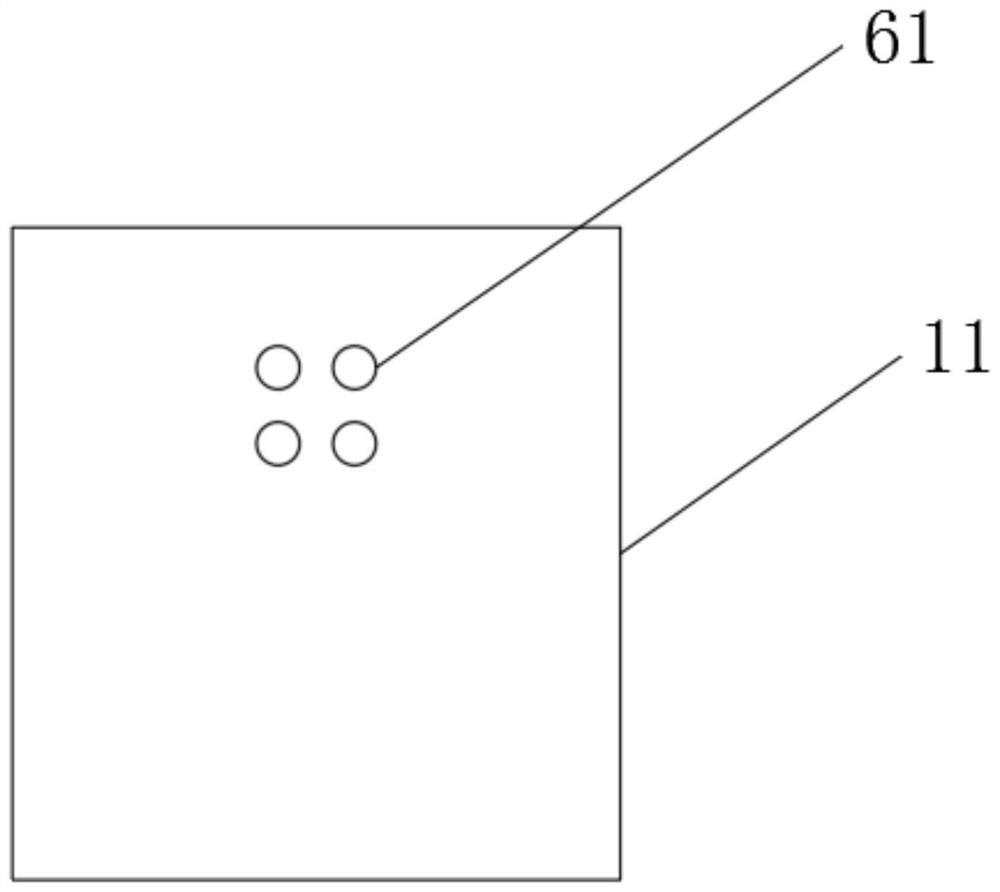
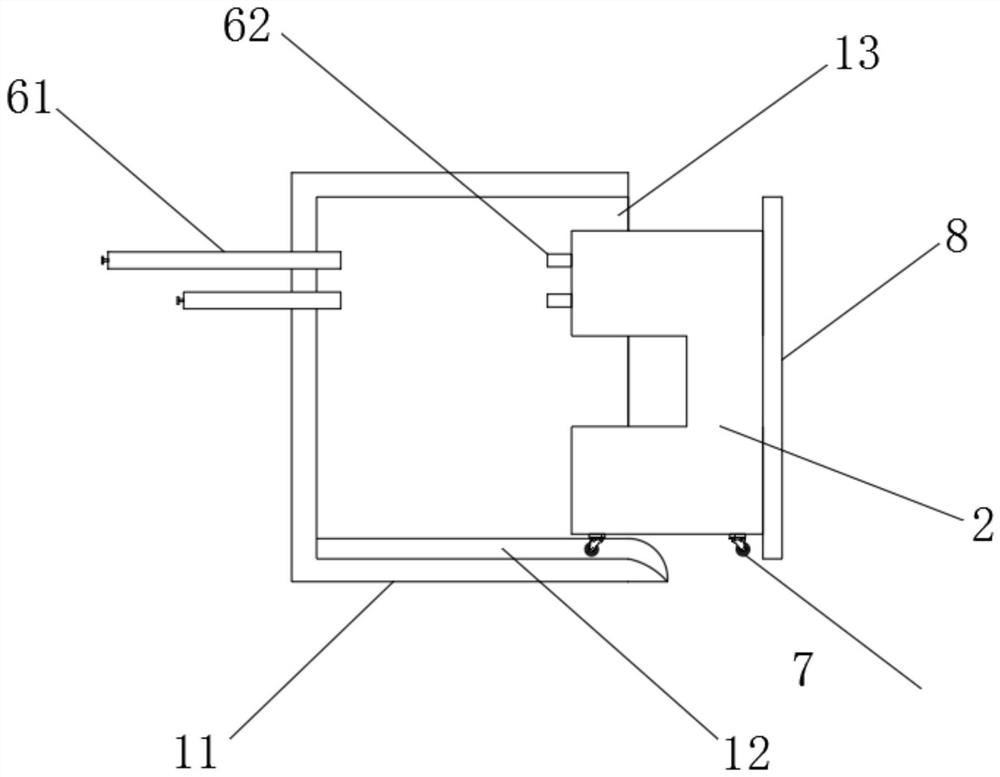
[0030] Such as Figure 1-5 As shown, a medium and high-speed marine diesel engine cylinder head processing device includes an assembly platform 1, a rough machining machine tool 2, a finishing machine tool 3, a No. 1 cutting fluid treatment system 4, a No. 2 cutting fluid treatment system 5, and a pipeline connection system 6;

[0031] The assembly platform 1 includes an assembly box 11 whose side wall is set as an opening 13, and a plurality of sets of guide rails 12 arranged at the bottom of the inner cavity of the assembly box 11. The roller 7 at the bottom of the lathe 3 cooperates. The roughing machine tool 2 / finishing machine tool 3 is fixedly provided with a baffle plate 8 on the side wall of the opening 13, and the top and bottom ends of the baffle plate 8 are in contact with the top and bottom ends of the opening 13, and two adjacent baffle plates 8 fit between.

[0032] The rough machining machine tool 2 and the finish machining machine tool 3 are clamped on the as...


PUM


Abstract

The invention relates to a medium-high speed ship diesel engine cylinder cover machining device, which comprises an assembling platform, a rough machining machine tool, a finish machining machine tool, a No.1 cutting fluid treatment system, a No.2 cutting fluid treatment system and pipeline connecting systems; the rough machining machine tool and the finish machining machine tool are connected to the assembling platform in a clamped mode and connected with the No.1 cutting fluid treatment system and the No.2 cutting fluid treatment system through the pipeline connecting systems correspondingly; and when the rough machining machine tool and the finish machining machine tool are connected with or separated from the assembling platform in a clamped mode, the pipeline connecting systems are driven to be communicated or closed correspondingly. The machine tool is connected with the assembling platform in a clamped mode, communication of cutting fluid input / output pipelines can be achieved while clamping is conducted, the pipelines are closed during disassembling, communication and closing of the pipelines can be achieved in the machine tool assembling and disassembling process, operation is rapid and convenient, machine tool disassembling and assembling do not need to be stopped, and continuous production of a production line is not affected.

Description

technical field [0001] The invention belongs to the technical field of processing diesel engine cylinder heads, and in particular relates to a processing device for medium and high-speed marine diesel engine cylinder heads. Background technique [0002] The diesel engine is the heart of a ship, and the diesel engine cylinder head is an important part of the diesel engine. If its performance is light, it will affect the decline of the mechanical efficiency of the diesel engine. loss. Therefore, higher requirements are put forward for the manufacturing process of AC111 cylinder head. It is very important to formulate a reasonable processing plan and process to ensure quality stability and improve support capabilities. [0003] In the existing diesel engine cylinder head production line, a cutting fluid treatment system is generally set up to process the cutting powder and cool the machining tool. In order to ensure the machining efficiency, the CNC machine tool needs to separ...

Claims


Application Information

Patent Timeline
Patent Type & Authority Applications(China)
IPC IPC(8): B23P23/02B23Q11/00
CPCB23P23/02B23Q11/00
Inventor 黄青松吴珠胜鲍万松
Owner ANQING CSSC MATING POWER
Learn More