SF6 multiple decomposition component detection device based on spatial light path coupling

A technology for decomposing components and detecting devices, which is used in measurement devices, color/spectral property measurement, material analysis by optical means, etc. Expand application scenarios, improve accuracy, and apply a wide range of effects

Pending Publication Date: 2021-10-29
WUHAN UNIV +1
View PDF10 Cites 1 Cited by
  • Summary
  • Abstract
  • Description
  • Claims
  • Application Information

AI Technical Summary

Problems solved by technology

In the prior art, the method of increasing the beam stroke is the spherical mirror reflection method. However, due to the size of the spherical mirror, the number of reflections of the beam is limited. When measuring trace gases, the effective stroke is still not achieved.
[0004] In addition, in Fourier transform infrared spectroscopy, the laser band of the laser is generally within a specific range, so it can only detect components within its band range. If multiple components need to be detected, multiple lasers and multiple Gas chamber, so the Fourier transform infrared spectrometer has a large volume, cannot adapt to the complexity of the field environment, is not easy to carry, and is difficult to implement on-site detection; although the electrochemical sensor is small in size and easy to carry, it has few detection components, and There is a problem of cross-interference between gas components

Method used


Image

  • SF6 multiple decomposition component detection device based on spatial light path coupling
  • SF6 multiple decomposition component detection device based on spatial light path coupling
  • SF6 multiple decomposition component detection device based on spatial light path coupling

Examples


Embodiment Construction

[0031] The application will be further described below in conjunction with the accompanying drawings. The following examples are only used to illustrate the technical solutions of the present invention more clearly, but not to limit the protection scope of the present application.

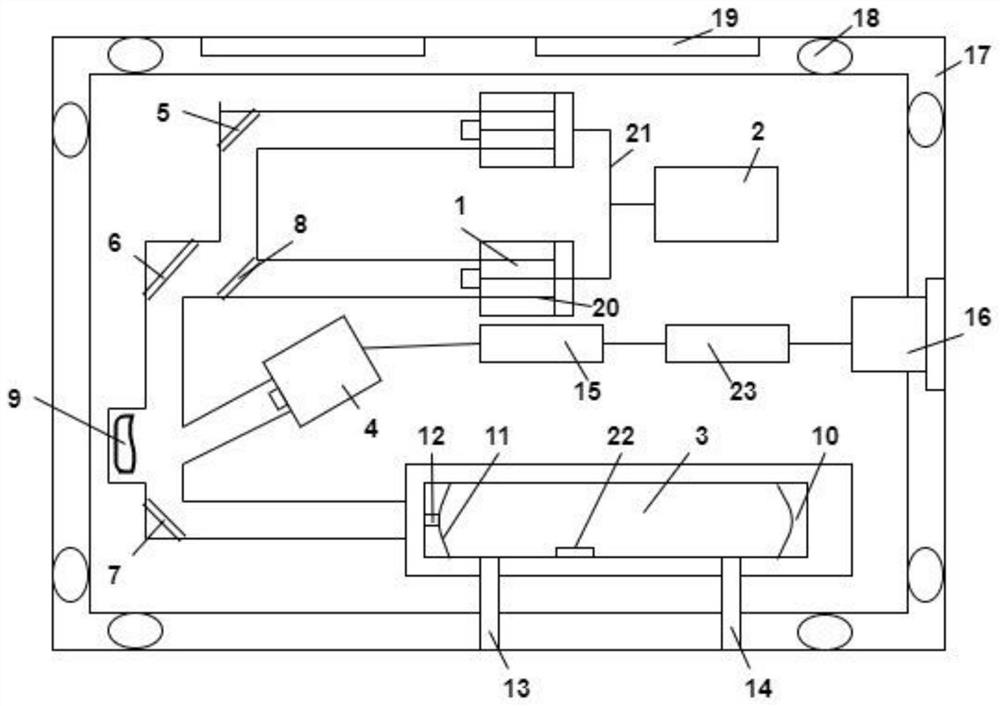
[0032] like figure 1 , a SF6 multi-decomposition component detection device based on spatial optical path coupling, including a laser light source, an absorption pool 3, and an MCT detector 4. The absorption pool 3 is a cylinder, one side of the absorption pool 3 is provided with a central perforated parabolic mirror 11, and the other side is provided with a parabolic mirror 10, and the infrared laser is injected into the absorption pool 3 through the small hole 12 on the central perforated parabolic mirror 11, The infrared laser is reflected several times between the two parabolic mirrors. During the reflection, the infrared laser is absorbed by the gas to be measured, and the reflected infrared ...


PUM


Abstract

The invention discloses an SF6 multiple decomposition component detection device based on spatial light path coupling. The SF6 multiple decomposition component detection device comprises a plurality of quantum cascade lasers, a signal controller, an absorption cell and an MCT detector, under the control of the signal controller, the central wave band of infrared laser emitted by each quantum cascade laser is consistent with the wave band of a decomposition component of a certain gas to be detected; the number of the quantum cascade lasers is consistent with the type number of the decomposition components of the gas to be detected; the quantum cascade laser emits infrared laser with different specific wavelengths into the absorption cell through an infrared laser light path according to the emitted infrared laser; and after being reflected for multiple times between the parabolic mirrors on the two sides of the absorption cell, the light is emitted out of the absorption cell and then is emitted into the MCT detector through the infrared laser light path. Only one absorption cell gas chamber is used to realize detection of multiple gas decomposition components; the influence of interference signals on the detection result is effectively reduced, the accuracy of the detection result is improved, processing can be carried out on multiple platforms, processing is convenient, and the application range is wide. The compact layout of the device gives consideration to sufficient heat dissipation space.

Description

technical field [0001] The present invention relates to the technical field of detection of gas decomposition components, more specifically, to a SF based on spatial optical path coupling 6 A variety of decomposition component detection devices. Background technique [0002] Sulfur hexafluoride (SF 6 ) gas is widely used in electrical equipment because of its excellent insulation and arc extinguishing properties. in SF 6 During production or long-term operation of gas-insulated equipment (GIS), various insulation defects may occur inside the equipment, including metal burrs, free conductive particles, and insulator defects in the equipment. The generation and development of these insulation defects lead to the SF in the equipment 6 The insulating gas decomposes to generate various SF 6 Decomposition products. Analysis of these products gives the SF 6 The internal insulation of the equipment is of great significance to the health status detection and maintenance of the...

Claims


Application Information

Patent Timeline
Patent Type & Authority Applications(China)
IPC IPC(8): G01N21/39G01N21/01
CPCG01N21/39G01N21/01
Inventor 胡耀垓张晓星张引朱正宜严进胡隽宇戴锋卞超程骏甘强陈轩张正东
Owner WUHAN UNIV
Why Eureka
Try Eureka