Corrosion-resistant saw-blade-shaped alloy milling cutter

A corrosion-resistant and alloyed technology, applied in the field of saw blade-shaped alloy milling cutters, can solve the problems of inability to meet the needs of users, poor corrosion resistance, lack of wear resistance and mechanical properties, achieve good heat dissipation effect, promote common Deposition, life-extending effect

Inactive Publication Date: 2021-11-05
常州市海伦工具有限公司
View PDF8 Cites 0 Cited by
  • Summary
  • Abstract
  • Description
  • Claims
  • Application Information

AI Technical Summary

Problems solved by technology

[0003] In the patent document with the Chinese patent application number CN201910930153.9, "A Corrosion-resistant Saw-shaped Alloy Milling Cutter" is disclosed. There are waste discharge grooves at equal intervals on the front of the blade, the inner wall of the waste discharge groove is fixedly connected with reinforcing ribs, and the outer side of the cutter head is fixedly connected with blades at equal intervals. The surface of the cutter head is adhered with a non-stick coating. One side is fixedly connected with the outer side of the cutter head, the outer side of the blade body is adhered with a heat-resistant coating, the outer side of the heat-resistant coating is adhered with an anti-corrosion coating, the outer side of the anti-corrosion coating is adhered with an anti-corrosion coating, and the outer side of the anti-corrosion coating is adhered with an anti-corrosion coating. The outer side of the wear-resistant coating is adhered with a wear-resistant coating, and the outer side of the wear-resistant coating is adhered with a strengthening coating". , lack of good wear resistance and mechanical properties, unable to meet the needs of users

Method used


Image

  • Corrosion-resistant saw-blade-shaped alloy milling cutter
  • Corrosion-resistant saw-blade-shaped alloy milling cutter
  • Corrosion-resistant saw-blade-shaped alloy milling cutter

Examples


Embodiment

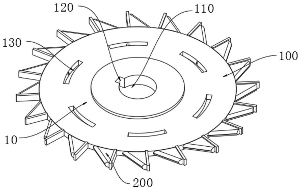
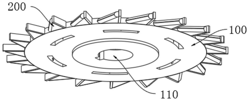
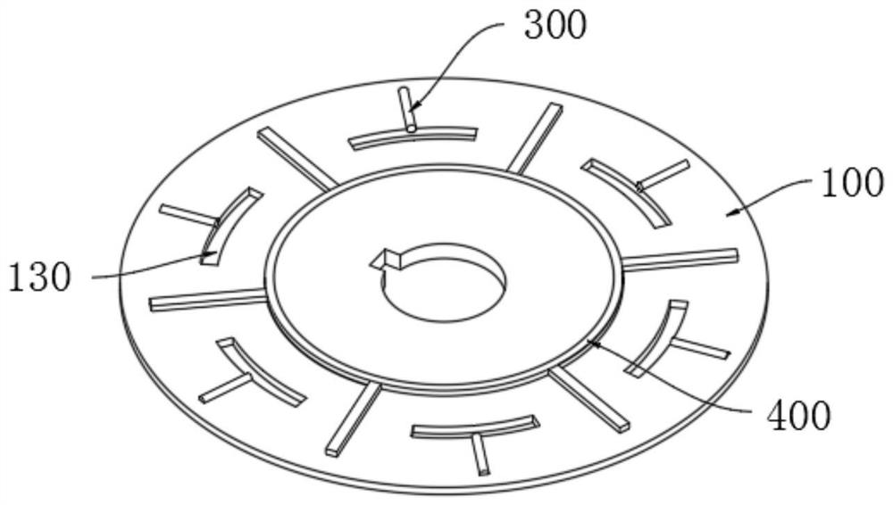
[0031] Please refer to Figure 1-5 As shown, a kind of corrosion-resistant saw blade-shaped alloy milling cutter comprises an alloy milling cutter body 10, and the alloy milling cutter body 10 includes a cutter head 100, and blades 200 are installed at equal intervals on the circumferential wall of the cutter head 100, and the cutter head 100 The center of the top is provided with an installation groove 110, and the inner wall of the installation groove 110 is provided with a pin groove 120, and the outer wall of the alloy milling cutter body 10 is deposited with a nanocomposite coating 20. In this embodiment, the installed installation groove 110 can realize For the installation of the alloy milling cutter body 10, the set pin groove 120 can prevent the alloy milling cutter body 10 from rotating during use, which improves the safety of the alloy milling cutter body 10 in use, and the deposited nanocomposite coating 20 can improve the alloy milling cutter body 10. The wear res...


PUM


Abstract

The invention relates to the technical field of mechanical metal machining cutters, in particular to a corrosion-resistant saw-blade-shaped alloy milling cutter. The corrosion-resistant saw-blade-shaped alloy milling cutter comprises an alloy milling cutter body, wherein the alloy milling cutter body comprises a cutter head, and cutting edges are arranged on the circumferential wall of the cutter head at equal intervals; a mounting groove is formed in the center of the top of the cutter head, a pin groove is formed in the inner wall of the mounting groove, and a nano-composite coating is deposited on the outer wall of the alloy milling cutter body; According to the corrosion-resistant saw-blade-shaped alloy milling cutter, the nano-composite coating is deposited on the alloy milling cutter body through cyclic voltammetry, so that the corrosion resistance and the friction resistance of the alloy milling cutter body are improved; heat generated in the using process of the alloy milling cutter body can be dissipated through heat conduction rods and arc-shaped grooves, and then the good heat dissipation effect on the alloy milling cutter body is achieved; and reinforcing ring ribs and reinforcing rod ribs are arranged in the alloy milling cutter body so that the mechanical strength of the alloy milling cutter body can be enhanced, the service life of the alloy milling cutter body is prolonged, and the quality of the alloy milling cutter body is effectively improved.

Description

technical field [0001] The invention relates to the technical field of mechanical metal processing knives, in particular to a corrosion-resistant saw blade-shaped alloy milling cutter. Background technique [0002] A milling cutter is a rotating tool with one or more teeth for milling. When working, each knife tooth cuts off the allowance of the workpiece intermittently in turn. Milling cutters are mainly used for machining planes, steps, grooves, forming surfaces and cutting workpieces on milling machines. The saw blade milling cutter is both a saw blade and a milling cutter, and it is a product of both. Most of the saw blade milling cutters are made of high-speed steel, cemented carbide and other materials with the same performance. [0003] In the patent document with the Chinese patent application number CN201910930153.9, "A Corrosion-resistant Saw-shaped Alloy Milling Cutter" is disclosed. There are waste discharge grooves at equal intervals on the front of the blade...

Claims


Application Information

Patent Timeline
Patent Type & Authority Applications(China)
IPC IPC(8): B23C5/08B23C5/28
CPCB23C5/08B23C5/28B23C2200/045B23C2228/10
Inventor 管亚飞
Owner 常州市海伦工具有限公司
Why Eureka
Try Eureka