
Solar micro gas turbine system

A micro gas turbine, solar energy technology, applied in the direction of using solar energy to generate mechanical power, solar thermal power generation, mechanical equipment, etc., can solve problems such as low thermal power generation efficiency

Active Publication Date: 2021-11-05
ZHEJIANG UNIV
View PDF11 Cites 0 Cited by
  • Summary
  • Abstract
  • Description
  • Claims
  • Application Information

AI Technical Summary

Problems solved by technology

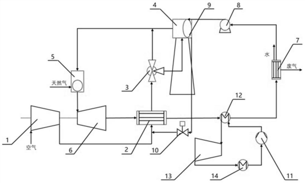
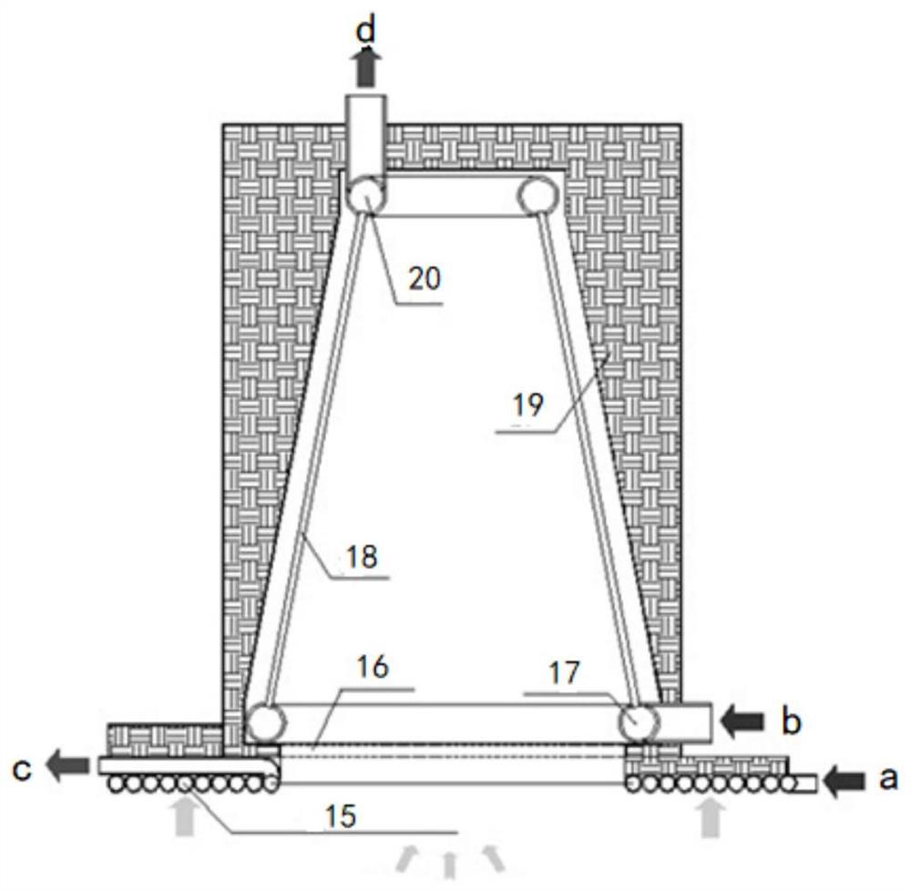
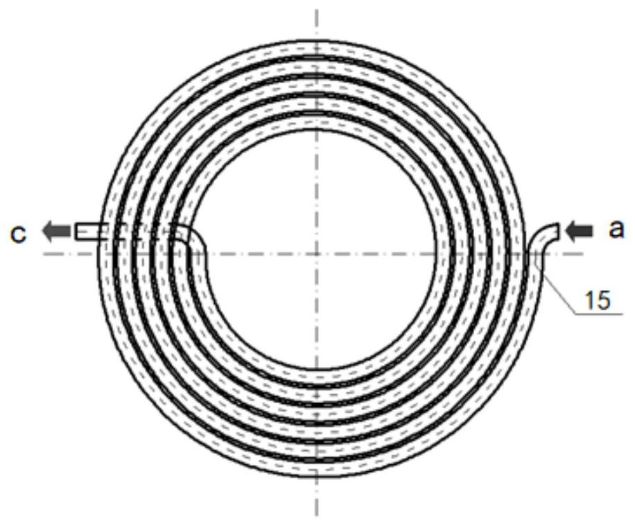
[0008] According to this technical proposal, by adding a solar high temperature air heat absorber in the cycle of the gas turbine system, increasing the temperature of the air entering the combustion chamber, and adding a water working medium air heat absorber, the daylight hole of the solar high temperature air heat absorber can be fully utilized The surrounding energy can improve the cut-off efficiency and solar energy utilization rate of the solar high-temperature air heat absorber, thereby reducing the consumption of fuel; in addition, reducing the excessive temperature of the combustion chamber by reinjecting steam can reduce the excess air intake and reduce the emission of the combustion chamber , reduce the power consumption of the compressor, improve the specific power and peak-shaving capacity of the system, solve the problems of low energy utilization rate of the heat-absorbing system in the tower solar-thermal power generation system and low efficiency of solar thermal power generation alone, and improve the power generation efficiency of the gas turbine system and energy utilization, while improving the system’s peak-shaving capability to achieve comprehensive utilization of multiple energy sources

Method used


Image

  • Solar micro gas turbine system
  • Solar micro gas turbine system
  • Solar micro gas turbine system

Examples


Embodiment Construction

[0026] The following will clearly and completely describe the technical solutions in the embodiments of the present invention with reference to the accompanying drawings in the embodiments of the present invention. Obviously, the described embodiments are only some, not all, embodiments of the present invention. Based on the embodiments of the present invention, all other embodiments obtained by persons of ordinary skill in the art without making creative efforts belong to the protection scope of the present invention.

[0027] Hereinafter, embodiments of the present invention will be described with reference to the drawings.

[0028] 1. Overall structure

[0029] figure 1 It is a schematic diagram of the overall structure of the solar micro gas turbine system provided in the embodiment of the present invention. Such as figure 1 As shown, the gas turbine system includes: compressor 1, regenerator 2, three-way valve 3, solar high-temperature air heat absorber 4, combustion c...


PUM


Abstract

The invention discloses a solar micro gas turbine system which comprises a gas compressor, a heat regenerator, a solar high-temperature air heat absorber with a daylighting hole, a combustion chamber, a gas turbine, a heat exchanger, a condenser, a water feeding pump and a water working medium heat absorber. After air is sucked by the gas compressor and is pressurized, steam heated by the water working medium heat absorber enters an air side inlet of the heat regenerator together, and air and steam mixed gas preheated by the heat regenerator enters the solar high-temperature air heat absorber to be further heated and then enters the combustion chamber. A traditional gas turbine system and a solar power generation system are combined, energy around the daylighting hole of the solar high-temperature air heat absorber is fully utilized, the cut-off efficiency of the heat absorber and the solar energy utilization rate are improved, fuel consumption is reduced, and meanwhile the problem of power supply intermittence of a solar power generation single system is also solved.

Description

technical field [0001] The invention relates to the technical field of gas turbines, in particular to a solar micro gas turbine system. Background technique [0002] Natural gas power generation is one of the most stable distributed energy supply methods. However, natural gas resources are non-renewable energy sources that are easily consumed, and the combustion of natural gas resources often produces a large amount of CO 2 and CO, adversely affecting the environment. This requires the development and use of some renewable clean energy as an alternative or supplement to natural gas. [0003] Solar energy is the best renewable energy that is inexhaustible all over the world. The development and utilization of solar energy, a clean, non-polluting renewable energy source, is of great significance for alleviating the current pressure on fossil energy and environmental pollution. . Solar thermal power generation technology is to convert solar thermal energy into electrical ene...

Claims


Application Information

Patent Timeline
IPC IPC(8): F03G6/06F01K27/00F01D15/10
CPCF03G6/064F01K27/00F01D15/10Y02E10/46
Inventor 肖刚帅威陈金利倪明江骆仲泱岑可法
Owner ZHEJIANG UNIV
Learn More