Multiband broadband radio frequency signal transmission device based on microwave photon link

A microwave photon link and radio frequency signal technology, which is applied in optical fiber transmission, electromagnetic wave transmission system, transmission system, etc., can solve the problems of complex electromagnetic compatibility design, complex system composition, and many spurious components, so as to reduce the amount of system equipment, Good system performance and optimized system design

Pending Publication Date: 2021-11-09
BEIJING INST OF ELECTRONICS SYST ENG
View PDF4 Cites 0 Cited by
  • Summary
  • Abstract
  • Description
  • Claims
  • Application Information

AI Technical Summary

Problems solved by technology

[0004] The present invention proposes a multi-band broadband radio frequency signal transmission device based on microwave photonic links to solve the complex system composition, poor signal concealment, large power consumption, and complex electromagnetic compatibility design faced during long-distance wireless transmission of multi-band broadband complex radio frequency signals , poor signal fidelity, many spurious components, limited bandwidth, etc.

Method used


Image

  • Multiband broadband radio frequency signal transmission device based on microwave photon link
  • Multiband broadband radio frequency signal transmission device based on microwave photon link
  • Multiband broadband radio frequency signal transmission device based on microwave photon link

Examples


Embodiment Construction

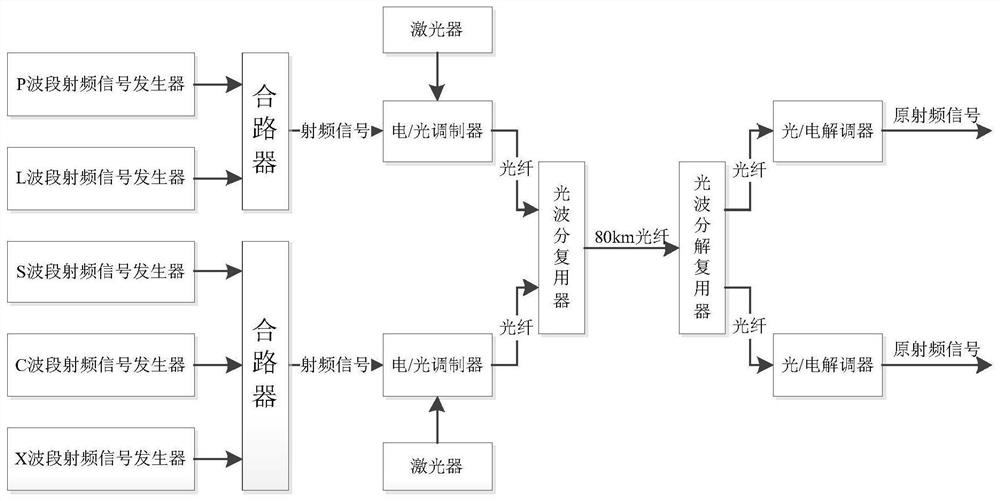
[0022] The invention proposes a multi-band broadband radio frequency signal transmission device based on a microwave photon link. figure 2 As shown, it includes a first group of band radio frequency signal generators, a second group of band radio frequency signal generators, a first combiner, a second combiner, a first electro-optic modulator, a second electro-optic modulator, an optical wavelength division multiplexer device, optical fiber, light-wave demultiplexer, first photoelectric demodulator, and second photoelectric demodulator.

[0023] At the sending end, the first group of radio frequency signal generators generates the first group of multi-band radio frequency signals, and the first group of multi-band radio frequency signals enter the first combiner for frequency division multiplexing to synthesize the first radio frequency signal, and the first radio frequency signal enter the first electro-optic modulator to form the first light wave signal (λ 1 ), the first l...


PUM


Abstract

The invention provides a multiband broadband radio-frequency signal transmission device based on a microwave photon link, a first group of multiband radio-frequency signals generated by a first group of radio-frequency signal generators are synthesized into a first path of radio-frequency signal, then the first path of radio-frequency signal enters a first electro-optical modulator and is modulated to form a first optical wave signal, and then the first path of radio-frequency signal enters an optical wavelength division multiplexer for optical wavelength division multiplexing; a second group of multi-band radio frequency signals generated by a second group of radio frequency signal generators are synthesized into a second path of radio frequency signals, the second path of radio frequency signals enter a second electro-optical modulator to be modulated to form second optical wave signals, and the second path of radio frequency signals enter an optical wavelength division multiplexer to be subjected to optical wavelength division multiplexing; the first light wave signal and the second light wave signal are synthesized into a beam of light signal after being subjected to light wavelength division multiplexing, the beam of light signal is sent to the light wave demultiplexer through an optical fiber, the light wave demultiplexer decomposes the first light wave signal and the second light wave signal, and then a first group of multiband radio frequency signals and a second group of multiband radio frequency signals are obtained. According to the invention, the problem of long-distance transmission of multiband broadband radio frequency signals can be solved.

Description

technical field [0001] The present invention relates to the technical field of multi-band radio frequency signals, in particular to a multi-band broadband radio frequency signal transmission device based on microwave photonic links, which is suitable for long-distance optical fiber transmission of multi-band broadband radio frequency analog signals, high-speed and large-capacity optical fiber communication, and ultra-wideband Signal generator, microwave photonics, electronic reconnaissance, ultra-wideband radar and other technical fields. Background technique [0002] The optical fiber transmission technology of radio frequency analog signal has the advantages of wide bandwidth, long transmission distance, low loss, good concealment, no interference from electromagnetic noise, small size, light weight, and low power consumption. Therefore, the radio frequency signal optical fiber transmission technology has a wide range of application requirements and prospects in the milita...

Claims


Application Information

Patent Timeline
IPC IPC(8): H04B10/25H04B10/2575H04J14/02
CPCH04B10/25H04B10/2575H04B10/25891H04J14/0278
Inventor 吕强王强梁悦川钟珲王景国方亮陈守稳王巾英
Owner BEIJING INST OF ELECTRONICS SYST ENG
Why Eureka
Try Eureka