
Laser cutting method for electronic ceramic substrate

A technology of laser cutting and electronic ceramics, which is applied in laser welding equipment, welding equipment, metal processing equipment, etc., can solve the problems of low cutting efficiency and crack generation, and achieve the effect of reducing thermal stress, reducing cracks, and reducing heat-affected zones

Pending Publication Date: 2021-11-16
FUJIAN HUAQING ELECTRONICS MATERIAL TECH
View PDF6 Cites 0 Cited by
  • Summary
  • Abstract
  • Description
  • Claims
  • Application Information

AI Technical Summary

Problems solved by technology

[0006] Therefore, in view of the above problems, the present invention provides a laser cutting method for electronic ceramic substrates, which solves the problems of cracks and low cutting efficiency caused by the laser cutting process in the prior art

Method used


Image

  • Laser cutting method for electronic ceramic substrate
  • Laser cutting method for electronic ceramic substrate
  • Laser cutting method for electronic ceramic substrate

Examples


Embodiment 1

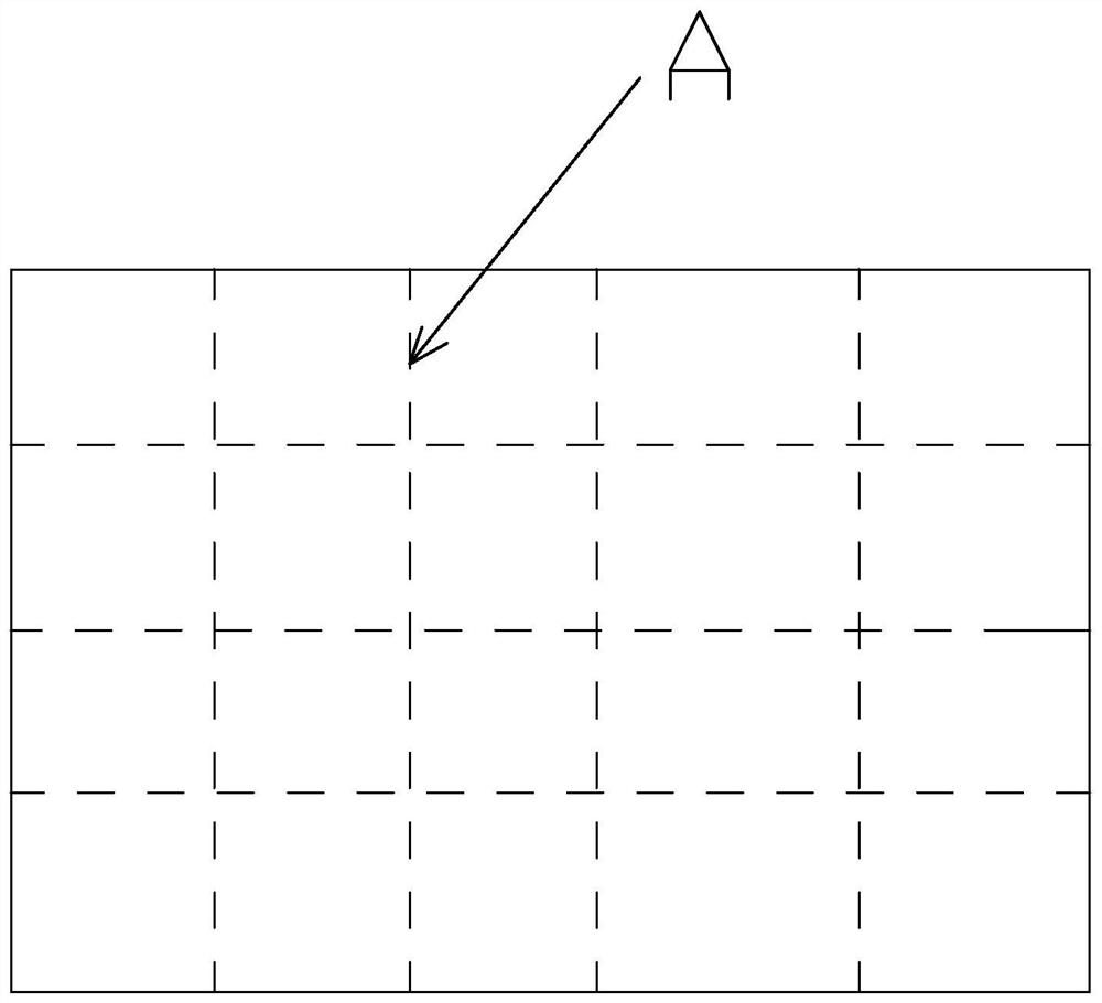
[0031] refer to figure 1 and figure 2 , a 3mm aluminum nitride ceramic substrate laser cutting method, comprising the following preparation steps:

[0032] (1) Place the ceramic substrate to be cut in CO 2 The cutting platform of the laser cutting machine is fixed;

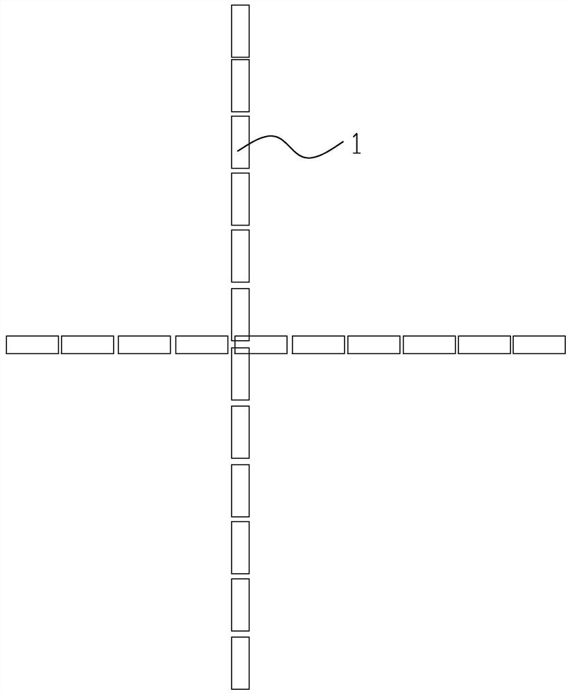
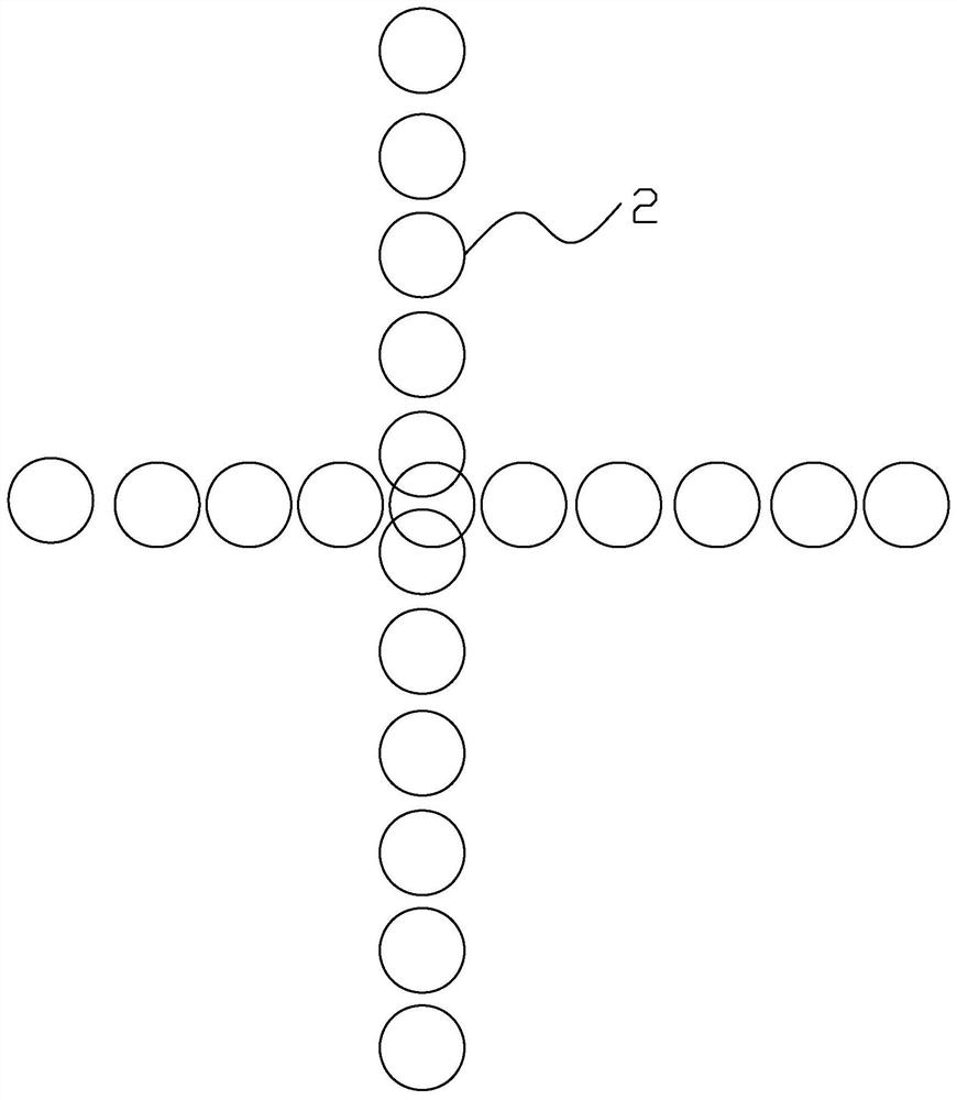
[0033] (2) Adjust CO 2 The parameters of the laser cutting machine: adjust the duty cycle to 45%, and the laser energy to 50J; by adjusting the parameters of the laser cutting machine, the laser spots are arranged in a continuous moment 1 at the slit of the ceramic substrate during laser cutting, and the cutting The depth of the slit is 0.05mm, and the width of the slit is 0.01mm; the cutting speed of the laser cutting machine is set to 2mm / s;

[0034] (3) Start the laser cutting machine to cut the ceramics. During cutting, auxiliary nitrogen gas is used to remove the molten material. The auxiliary gas is sprayed into the slit through the auxiliary gas nozzle. The auxiliary gas nozzle is non-coaxial auxiliary...

Embodiment 2

[0039] A laser cutting method for electronic alumina ceramic substrates, using a laser cutting processing system for cutting processing, using a CO with an output power of 250W 2 For the laser cutting machine 5, the output mode of the laser is pulsed. The specific steps are:

[0040] (1) Place the alumina ceramic substrate to be cut on the cutting platform 6 of the laser cutting machine and fix it; the thickness of the alumina ceramic substrate is 2mm, and the purity of alumina is 96%;

[0041] (2) Adjust the parameters of the laser cutting machine: adjust the duty cycle to 47%, the laser energy to 35J; the pulse frequency to 50hz;

[0042] (3) Start the laser cutting machine to cut the ceramics, the depth of the kerf is 0.07mm, and the width of the kerf is 0.02mm. Non-coaxial sub-axis gas nozzles are used to assist in cutting. Specifically, refer to Figure 5, the diameter of the nozzle is 1.5mm, nitrogen is used as the auxiliary gas, the gas pressure is 25pa, the cutting ...


PUM

PropertyMeasurementUnit
Thicknessaaaaaaaaaa
Angleaaaaaaaaaa
Angleaaaaaaaaaa

Abstract

The invention relates to the technical field of laser cutting, provides a laser cutting method for an electronic ceramic substrate, and solves the problems of crack generation and low cutting efficiency caused by a laser cutting process in the prior art. The method comprises the following preparation steps that (1) a ceramic substrate to be cut is placed and fixed on a cutting platform of a laser cutting machine; (2) parameters of a laser cutting machine are adjusted, wherein the duty ratio is adjusted to be 45%-50%, and the laser energy is adjusted to be 20-52 J; the parameters of the laser cutting machine are adjusted, so that laser spots are continuously and rectangularly arranged at the kerf of the ceramic substrate during laser cutting, the depth of the kerf is 0.05-0.09 mm, and the width of the kerf is 0.01-0.02 mm; and (3) the laser cutting machine is started to cut the ceramic.

Description

technical field [0001] The invention relates to the technical field of laser cutting, in particular to a laser cutting method for an electronic ceramic substrate. Background technique [0002] The traditional cutting of hard and brittle materials uses high-speed rotating blades or diamonds to pre-cut the ceramic sheet, and then breaks it according to the direction of the cut. Conventional machining methods easily lead to cutting powder splashing, micro-cracks, and some even fragments, especially at the intersection of scribing lines, which affect the strength and function, and the surface quality of the cutting edge is low, requiring secondary processing. cause blade wear. [0003] In order to change the above situation, laser cutting machines have appeared on the market. At present, laser cutting has been widely used in industrial sectors such as automobiles, rolling stock manufacturing, aviation, chemical industry, light industry, electronics, petroleum and metallurgy. Th...

Claims


Application Information

Patent Timeline
IPC IPC(8): B23K26/38B23K26/142B23K26/60B23K26/70
CPCB23K26/38B23K26/142B23K26/60B23K26/703
Inventor 杨大胜施纯锡
Owner FUJIAN HUAQING ELECTRONICS MATERIAL TECH
Learn More