Heat dissipation structure capable of regulating and controlling flow in partitioned manner and preparation method of heat dissipation structure

A technology of heat dissipation structure and heat dissipation unit, applied in semiconductor/solid-state device parts, semiconductor devices, electrical components, etc., can solve the problems of difficulty in using embedded microfluidic heat dissipation structure, increase system complexity, etc., to strengthen cooling performance, improve Utilization rate, the effect of improving energy consumption ratio

Pending Publication Date: 2021-11-16
PEKING UNIV +1
View PDF0 Cites 0 Cited by
  • Summary
  • Abstract
  • Description
  • Claims
  • Application Information

AI Technical Summary

Problems solved by technology

Although this method will not cause waste of pump work, it will increase the complexity of the system
Especially in the case of large-scale chiplet integration, if there are n*n regulatory regions, you need to set n 2 liquid inlet and n 2 liquid outlet, and equipped with n 2 control valves, which greatly increases the complexity of the system, making it difficult to apply this method to embedded microfluidic cooling structures.

Method used


Image

  • Heat dissipation structure capable of regulating and controlling flow in partitioned manner and preparation method of heat dissipation structure
  • Heat dissipation structure capable of regulating and controlling flow in partitioned manner and preparation method of heat dissipation structure
  • Heat dissipation structure capable of regulating and controlling flow in partitioned manner and preparation method of heat dissipation structure

Examples


preparation example Construction

[0065] The present invention also provides a preparation method for the above-mentioned heat dissipation structure, which includes the following steps.

[0066] Firstly, a cover plate structure comprising a first heat dissipation unit array is prepared, so that each of the first heat dissipation units is provided with an embedded micro-channel.

[0067] The embedded micro-channel can be formed according to the design of the embedded micro-channel of the first heat dissipation unit as described above.

[0068] In a specific embodiment, the cover plate structure is integrally formed, and the entire substrate is processed by a photolithography process, an etching process, a milling process, an etching process or a combination thereof, so as to obtain the The cover plate structure of the cell array. The substrate can be a material with high thermal conductivity, such as silicon, diamond, metal (such as copper), and the like.

[0069] In another specific embodiment, the cover pla...

Embodiment 1

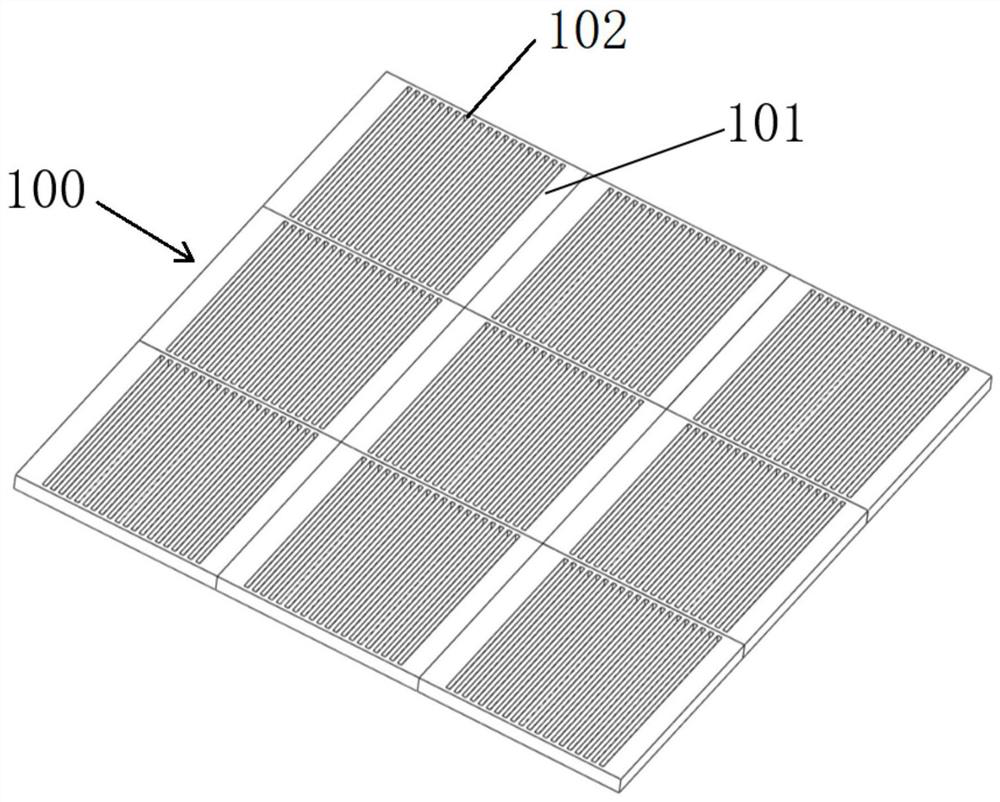
[0083] First, the heat dissipation area of ​​the heat source is divided into 3*3 sub-areas, and the first heat dissipation unit array is designed according to these sub-areas, wherein the area of ​​the first heat dissipation unit 101 is 5mm*5mm, and the embedding in each first heat dissipation unit 101 The micro-channels 102 are independent of each other and have the same structural features. Then, the embedded micro-channel 102 is formed on the copper plate by milling cutter processing technology, so as to obtain the cover plate structure 100, such as figure 1 shown.

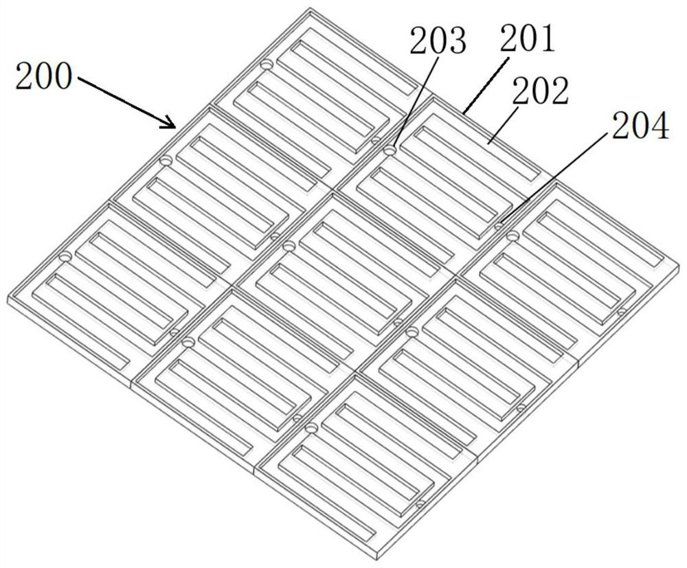
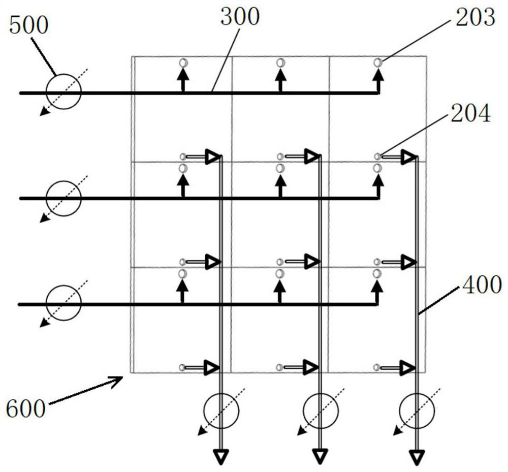
[0084] The second heat dissipation unit array is formed on the copper plate by using milling cutter processing technology and drilling technology, so as to obtain the bottom plate structure 200, as shown in figure 2 As shown, the second heat dissipation unit 201 includes a manifold channel 202 , a liquid inlet 203 and a liquid outlet 204 , and the manifold channels 202 in each second heat dissipation unit 201...

Embodiment 2

[0088] Carry out according to the method for embodiment 1, difference is:

[0089] 1) The structural features of the embedded micro-channel 102 of the first heat dissipation unit 101 located in the center of the first heat dissipation unit array are minimized so as to increase the convective heat transfer coefficient and enhance the local cooling capacity. The obtained cover plate structure 100 is as follows Figure 4 shown;

[0090] 2) Make the manifold passage 202 structural feature (ie width) of the second heat dissipation unit 201 located in the center of the second heat dissipation unit array the smallest, and the number of manifold passages is the largest; make the second heat dissipation unit located at the four corners of the second heat dissipation unit array The structural characteristics of the manifold channels are the largest, and the number of manifold channels is the least. The resulting base plate structure 200 is as follows Figure 5 shown;

[0091] 3) After...


PUM


Abstract

The invention relates to a heat dissipation structure capable of regulating and controlling the flow in a partitioned manner. The flow resistance is adjusted by adjusting the connection relation between a liquid inlet pipeline and a liquid inlet, the connection relation between a liquid outlet pipeline and a liquid outlet, and the structural characteristics and parallelism of embedded micro-channels and manifold channels in different regions in the heat dissipation structure, and the number of pressure regulation and control structures required by flow regulation and control can be reduced to a great extent. According to the heat dissipation structure, the heat dissipation performance of different areas in the heat dissipation structure can be dynamically adjusted and controlled by adjusting the pressure intensity value of the pressure adjusting and controlling structure, and compared with a traditional single-valve flow channel structure, the utilization rate of pump work can be increased, and the energy consumption ratio of a heat dissipation system can be increased. According to the invention, a small-size, high-parallelism and small-flow-resistance manifold channel structure is designed for the area with the high heat dissipation performance requirement in the heat dissipation structure, the cooling performance is enhanced, meanwhile, pressure drop regulation and control are more effective through small flow resistance, and the modulation proportion is increased. In addition, the invention also relates to a preparation method of the heat dissipation structure.

Description

technical field [0001] The invention relates to the field of chip heat dissipation, in particular to a heat dissipation structure capable of zone-adjustable flow and a preparation method thereof. Background technique [0002] Liquid cooling is a technology that cools high-heating power modules in electronic devices through the properties of liquids. It is used for chip modules with large thermal design power consumption, and is mainly used for cooling high-power chips. Because liquids have a larger specific heat capacity than gases, and generally have a larger convective heat transfer coefficient when liquids and solid surfaces move relative to each other, liquid cooling can achieve smaller thermal resistances between transistor junction temperatures and ambient temperatures . [0003] In the design and testing process of liquid cooling radiators, the heat source is often a simulated heat source with uniform heat generation, or a heat generation model with a small number of...

Claims


Application Information

Patent Timeline
Patent Type & Authority Applications(China)
IPC IPC(8): H01L23/473H01L23/34
CPCH01L23/473H01L23/34
Inventor 王玮杨宇驰杜建宇
Owner PEKING UNIV
Why Eureka
Try Eureka