
Light force fusion tail end clamping device and positioning control method thereof

A gripper and positioning technology, which is applied in the field of optical force fusion end gripper and its positioning control, can solve the problems of inaccurate adjustment of the robot's pose, difficulty in hitting the target, and affecting positioning, etc., to achieve convenient clamping and disassembly operations Fast, reduce accidental errors, and speed up recovery

Pending Publication Date: 2021-11-19
SOUTH CHINA UNIV OF TECH
View PDF10 Cites 2 Cited by
  • Summary
  • Abstract
  • Description
  • Claims
  • Application Information

AI Technical Summary

Problems solved by technology

The first problem is that during the puncture surgery, due to the physiological movement of human organs or tissues, the target point will move and change its position, which makes it difficult for the puncture surgery robot based on optical guidance to hit the target point only by optical tracking. During thoracic and abdominal puncture, respiratory movement will cause the visceral puncture target to move, and muscle contraction and involuntary limb movement during the patient's pain response will also affect positioning and needle puncture
The second problem is that the optical tracking system used can only judge the situation of the puncture needle in the human body through the optical markers installed at the end of the robot arm, and then adjust the robot's pose; but in fact, the puncture needle itself is too long to easily cause Elastic deformation will generate an interaction force with the surrounding tissue during the puncture process, but the optical tracking system cannot detect this interaction force, so there is no corresponding force compensation, the adjustment of the robot’s pose is not accurate enough, and the feedback optical information is also inaccurate. Accurate planning and control cannot be obtained, resulting in a serious deviation between the actual puncture trajectory and the planned trajectory, making the interaction force between the puncture needle and the surrounding tissue stronger, so that the puncture needle inside and outside the skin will undergo elastic deformation, In severe cases, there will be visible bending, and eventually human tissue, skin or organs may be damaged.

Method used


Image

  • Light force fusion tail end clamping device and positioning control method thereof
  • Light force fusion tail end clamping device and positioning control method thereof
  • Light force fusion tail end clamping device and positioning control method thereof

Examples


Embodiment Construction

[0056] The present invention will be further described below in conjunction with specific implementation examples, but the embodiments of the present invention are not limited thereto.

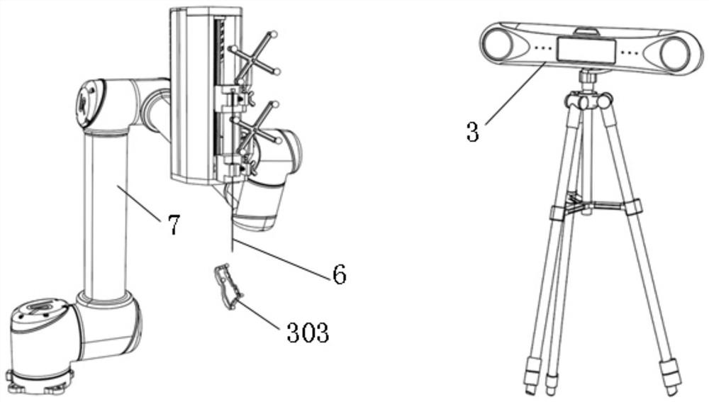
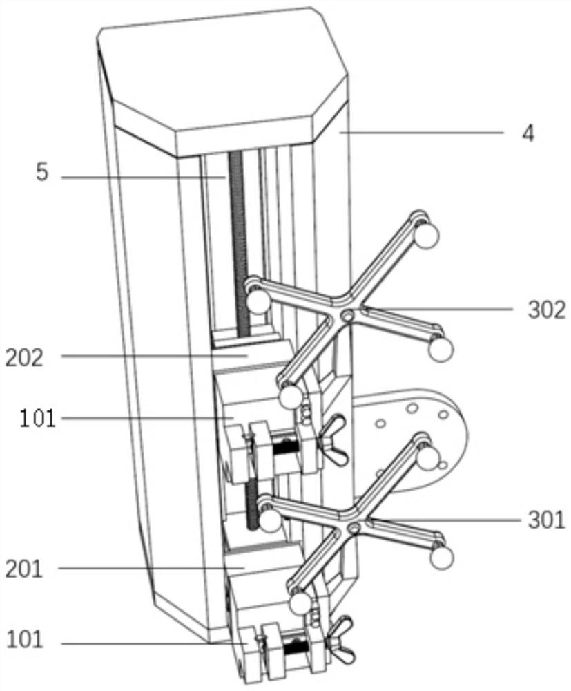
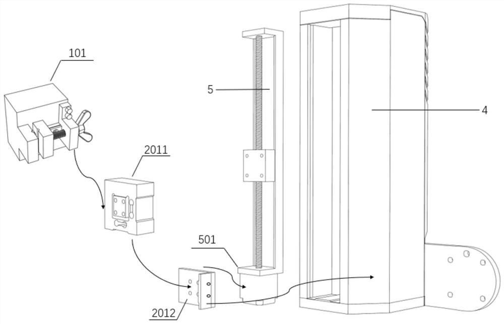
[0057] see Figure 1 to Figure 6 As shown, this embodiment provides an optical force fusion terminal holder, including a near-infrared optical positioner 3 and a clamping mechanism installed at the end of a six-degree-of-freedom mechanical arm 7. The clamping mechanism includes a force-bearing puncture needle Acquisition device, puncture needle clamping device, packaging box 4 and motor sliding module 5 packaged in the packaging box 4; said puncture needle force collection device includes puncture needle lateral force collection end 201 and a lateral force collection end located at the puncture needle The radial force collection end 202 of the puncture needle above 201, the lateral force collection end 201 of the puncture needle includes a first three-dimensional force sensor 2011 and a first ...


PUM


Abstract

The invention discloses a light-force fusion tail end clamping device and a positioning control method thereof. The light-force fusion tail end clamping device comprises a near-infrared optical positioning instrument and a clamping mechanism, the clamping mechanism comprises a puncture needle stress collecting device, a puncture needle clamping device, a packaging box and a motor sliding module packaged in the packaging box; the puncture needle stress collecting device comprises a puncture needle transverse force collecting end and a puncture needle radial force collecting end. The puncture needle clamping device comprises two clamping assemblies fixed to the puncture needle transverse force collecting end and the puncture needle radial force collecting end respectively. The near-infrared optical positioning instrument is provided with a first positioning tool, a second positioning tool and a positioning plate which are each provided with reflective mark points. According to the invention, the puncture needle can be fixed and moved as required, and the acting force on the puncture needle can be fed back in time, so that the real-time adjustment of the pose of the puncture surgical robot is realized; and on the basis of judging and adjusting the pose of the robot through the near-infrared optical positioning instrument, the operation accuracy and safety of the puncture operation robot in an operation are further improved.

Description

technical field [0001] The invention relates to the technical field of optical navigation and force feedback control of surgical robots, in particular to an optical force fusion end gripper and a positioning control method thereof. Background technique [0002] With the advancement of robot technology and the innovation of medical technology, the combination of medicine and robotics has become one of the development trends of the medical industry. Medical robots refer to a variety of robotic devices used in surgery, medical training, rehabilitation, prostheses, and assistance for the disabled. According to different service objects, it can be divided into medical surgical robots, rehabilitation robots, and elderly and disabled robots. As one of the branches of medical surgical robots, the puncture robot is a medical robot dedicated to minimally invasive surgery. It generally consists of four parts: a robotic arm, an imaging device, a spatial positioning system, a workstatio...

Claims


Application Information

Patent Timeline
Patent Type & Authority Applications(China)
IPC IPC(8): A61B34/30A61B17/34A61B90/13A61B34/20
CPCA61B34/30A61B34/70A61B17/3403A61B90/13A61B34/20A61B2034/2055
Inventor 杨荣骞张文龙赵心怡马家兴曹晓利
Owner SOUTH CHINA UNIV OF TECH
Learn More