Continuous nitration reaction device and method for benzene ring nitration

A technology of nitrification reaction device and nitrification reactor, which is applied in the direction of chemical instruments and methods, chemical/physical/physical chemical fixed reactors, feeding devices, etc., which can solve the problems of weakening mixing effect, uneven residence time, and reducing heat transfer Coefficient and other issues to achieve the effect of increasing the possibility of explosion, safe and reliable production process, and enhancing mass transfer and heat transfer

Active Publication Date: 2021-11-26
唐山金坤化工有限公司
View PDF16 Cites 2 Cited by
  • Summary
  • Abstract
  • Description
  • Claims
  • Application Information

AI Technical Summary

Problems solved by technology

[0005]1. When the kettle-type nitration reactor is used for the generation process of thermal nitration reaction, the heat transfer is mainly through the outer jacket of the kettle, and when the heat transfer of the jacket cannot meet the requirements It is necessary to install a heat transfer coil in the kettle to increase the heat transfer area. Adding a heat transfer coil will reduce the stirring diameter, weaken the mixing effect, and reduce the heat transfer coefficient. Therefore, the overall heat transfer effect of the kettle-type nitration reactor is not good.
[0006]2. When the tank-type nitration reactor is used for batch reaction, it generally adopts drop-feed feeding, and local overheating and uneven concentration distribution in the tank will occur at the feeding site, resulting in Product quality is not high and production capacity is limited
[0007]3. When the tank-type nitration reactor is used in the continuous nitration reaction process, multiple tanks need to be connected in series. Overnitration is not easy to control and the production process is complicated
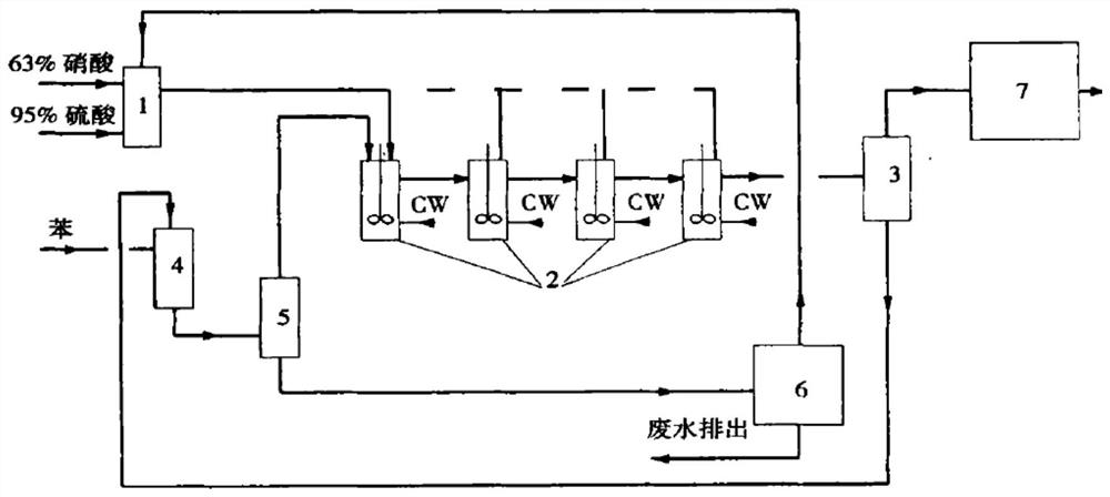
But in traditional nitration process, the main shortcoming of above-mentioned technological process is: for controlling reaction temperature nitration time is long, along with the concentrated sulfuric acid in the carrying out mixed acid of nitration reaction is diluted, the nitrification ability weakens in the late stage of reaction, and by-product increases, and for nitration Equipment requires sufficient cooling area

Method used


Image

  • Continuous nitration reaction device and method for benzene ring nitration
  • Continuous nitration reaction device and method for benzene ring nitration
  • Continuous nitration reaction device and method for benzene ring nitration

Examples


Embodiment Construction

[0069] The present invention will be further described below in conjunction with specific embodiments, and the advantages and characteristics of the present invention will become clearer along with the description. However, these embodiments are only exemplary and do not constitute any limitation to the scope of the present invention. Those skilled in the art should understand that the details and forms of the technical solutions of the present invention can be modified or replaced without departing from the spirit and scope of the present invention, but these modifications and replacements all fall within the protection scope of the present invention.

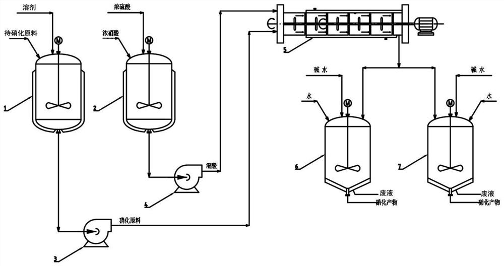
[0070] Please refer to figure 2 , figure 2 It is a flow chart of the nitration reaction process of the present invention. First, after the excess raw material to be nitrated and the solvent are fully mixed in the nitrated raw material tank 1, the nitrated feed pump 3 is pumped to the continuous nitrated reactor 5, and at t...


PUM


Abstract

The invention discloses a continuous nitration reaction device and method for benzene ring nitration. The device comprises a nitration raw material tank, a mixed acid preparation tank, a nitration feeding pump, a mixed acid feeding pump, a continuous nitration reactor and two coarse nitrate product separation tanks. With the continuous nitration reaction device and method for benzene of the invention adopted, the continuous nitration production is realized. The operation flexibility of the device is high, stable operation can be realized in a wider yield range, the production efficiency is high, the product quality is good, few byproducts are produced, the energy consumption and the raw material consumption are low, and the production process is safe and reliable.

Description

technical field [0001] The invention relates to a continuous nitration reaction device and method for nitration of benzene rings, and belongs to the field of nitration production technology. Background technique [0002] The reaction of introducing nitro groups into the aromatic ring is called nitration reaction. Nitrification is an electrophilic substitution. Nitrification reaction is a strong exothermic reaction. Its heat of reaction is 142KJ / mol. At the same time as the reaction, the sulfuric acid in the mixed acid is reacted to generate water Dilution also produces dilution heat (about 7% to 10% of reaction heat). If the reaction temperature continues to rise, side reactions will be caused, a large amount of nitric acid will be decomposed, and nitrophenol by-products will increase. These phenol by-products are the main cause of accidents in the production of nitrobenzene. At the same time, the nitrification reaction is a heterogeneous reaction, and the reaction occurs a...

Claims


Application Information

Patent Timeline
Patent Type & Authority Applications(China)
IPC IPC(8): B01J19/18B01J19/00B01J4/00C07C201/08C07C205/06
CPCB01J19/18B01J19/0053B01J19/0013B01J4/001C07C201/08C07C205/06
Inventor 潘锦顾伟超陈卓周田田袁沩明李亮
Owner 唐山金坤化工有限公司
Why Eureka
Try Eureka