
Inductor manufacturing method and inductor

A manufacturing method and inductor technology, which is applied in the direction of inductor/transformer/magnet manufacturing, transformer/inductor coil/winding/connection, circuit, etc., which can solve the problems of large inductor DCR, easy to be affected by external environment, and high risk of circuit breaker

Pending Publication Date: 2021-11-30
HENGDIAN GRP DMEGC MAGNETICS CO LTD
View PDF0 Cites 0 Cited by
  • Summary
  • Abstract
  • Description
  • Claims
  • Application Information

AI Technical Summary

Problems solved by technology

[0005] The object of the present invention is to provide a method for manufacturing an inductor and an inductor, so as to solve the problems in the prior art that the DCR of the inductor is large, the risk of circuit breakage is high, and it is easily affected by the external environment

Method used


Image

  • Inductor manufacturing method and inductor
  • Inductor manufacturing method and inductor
  • Inductor manufacturing method and inductor

Examples


Embodiment 1

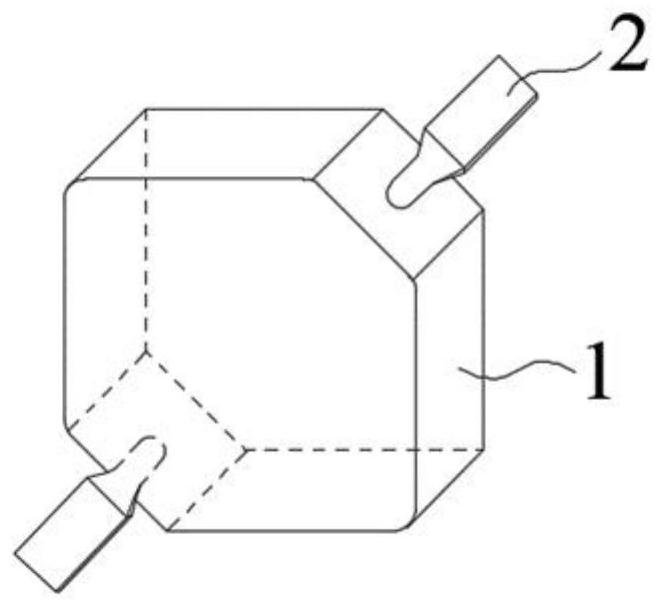
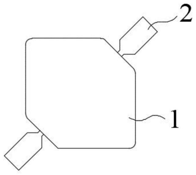
[0044] The existing method for manufacturing the winding of an integrally formed inductor usually uses spot welding to connect the three electrodes. One method is to place the spot-welded wire group and the three electrodes in the mold cavity, and then place them in the mold cavity. Fill the metal magnetic powder into the die-casting molding, and finally become a finished product. Another way is to put the winding into the mold cavity, fill the metal magnetic powder into the mold cavity, and then extend the pin 2 of the winding out of the magnetic core. Body 1, and welded with 3 electrodes. However, if spot welding is used to connect pin 2 and electrode 3, due to the small solder joints, both of the above two methods will lead to a large contact resistance between the winding and the electrode 3, which will lead to the DC resistance of the finished inductor (DCR, Directive Current Resistance) is relatively large, which brings large conduction loss, and because the shock resist...

Embodiment 2

[0068] This embodiment provides a method for manufacturing an inductor. The difference between the method for manufacturing an inductor and the method for manufacturing an inductor in Embodiment 1 is that:

[0069] Step S101 in this embodiment includes:

[0070] S1011. Winding wire group: wind the coil according to a certain wire diameter and number of turns to form a wire group that meets the requirements of inner and outer diameter and height, and remove the insulating layer at both ends of the wire group, and use it as pin 2 of the wire group;

[0071] S1012, welding the pin 2 and the electrode 3, then placing the wire group in the mold cavity, and leading the pin 2 to the outside of the mold cavity;

[0072] S1013, filling the mold cavity with magnetic material, and press molding to obtain the magnetic core body 1 .

[0073] Step S102 includes: bending and bonding the welded pins 2 and electrodes 3 to the surface of the magnetic core body 1 .

[0074] Such as Figure 5 ...


PUM


Abstract

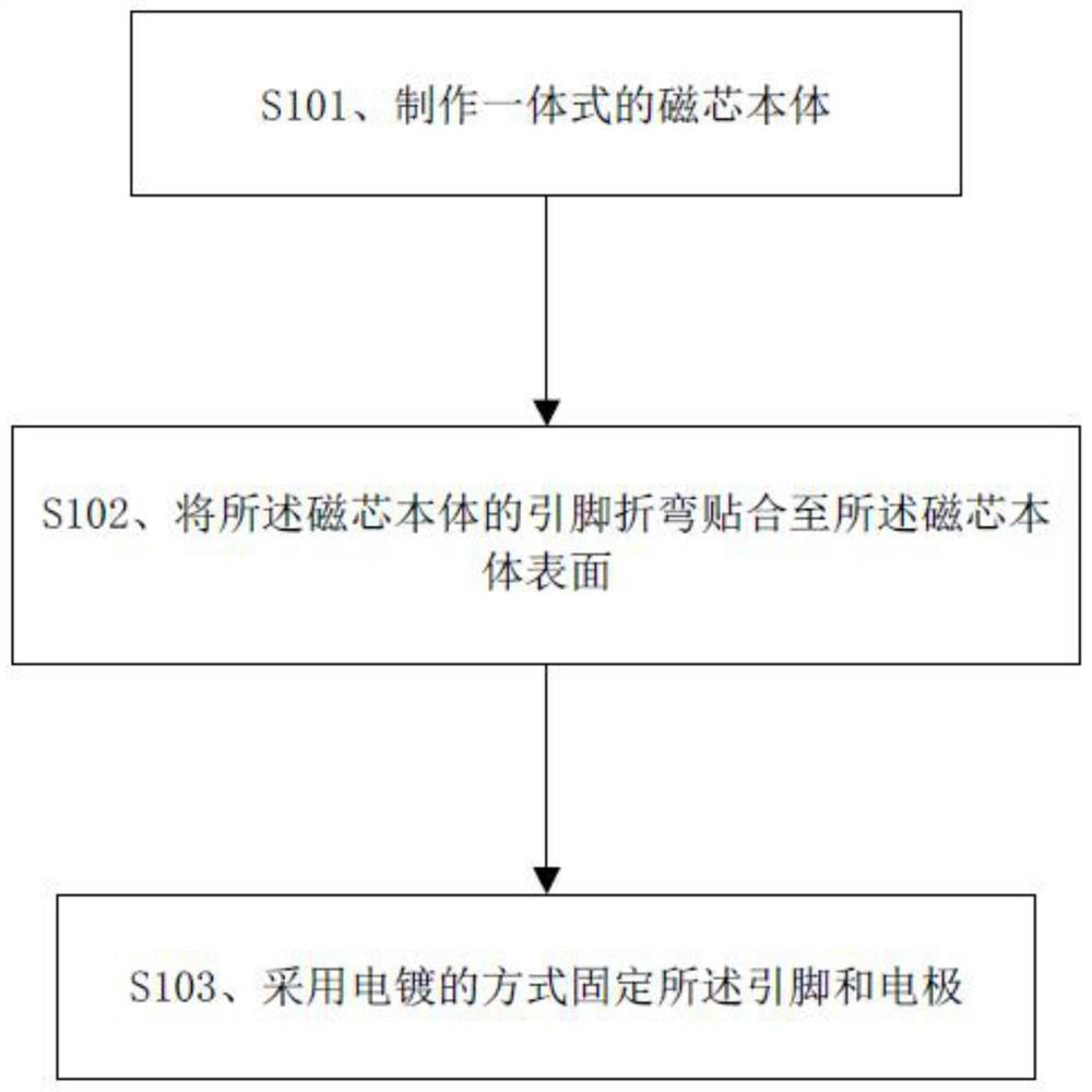
The invention relates to the technical field of soft magnetic product manufacturing, and particularly discloses an inductor manufacturing method and an inductor. The inductor manufacturing method comprises the steps of S101, manufacturing an integrated magnetic core body; S102, bending pins of the magnetic core body, and attaching the pins to the surface of the magnetic core body; and S103, electroplating and fixing the pins on electrodes in an electroplating manner. The pins of the magnetic core body are bent and attached to the surface of the magnetic core body, the pins and the electrodes are fixed in an electroplating mode, the contact area of the pins and the electrodes is increased, the contact resistance is small, the DCR is small, open circuit is not prone to happening, a protective layer is formed outside the winding and the electrodes after electroplating, contact between the winding and the electrodes and the external environment is isolated, and failure is not prone to happening. The inductor manufactured through the inductor manufacturing method is small in contact resistance, small in DCR and not prone to open circuit, the protective layer is formed outside the windings and the electrodes, and the inductor is not prone to failure and high in reliability.

Description

technical field [0001] The invention relates to the technical field of manufacturing soft magnetic products, in particular to an inductor manufacturing method and the inductor. Background technique [0002] As a common electronic component, inductors are widely used in electronic circuits. The existing one-piece inductors generally include a soft magnetic core body and windings. The windings are made according to a certain wire diameter, number of turns, winding inner and outer diameters and heights, and are placed in the mold cavity, embedded in metal magnetic powder for die-casting. made. Compared with traditional inductors, integrated inductors have higher inductance and smaller leakage inductance. The windings of conventional one-piece inductors are usually connected to the electrode sheets by spot welding. One way is to place the spot-welded wire group and electrode sheets in the mold cavity, and then fill the mold cavity with metal magnetic powder for die-casting. M...

Claims


Application Information

Patent Timeline
IPC IPC(8): H01F41/00H01F41/10H01F27/29H01F27/34
CPCH01F41/00H01F41/10H01F27/29H01F27/34
Inventor 郭宾贾俊康金志洪
Owner HENGDIAN GRP DMEGC MAGNETICS CO LTD
Learn More