Galvanometer scanning laser welding method based on variable light spots

A galvanometer scanning and laser welding technology, which is applied in laser welding equipment, welding equipment, metal processing equipment, etc., can solve problems such as limited capacity, and achieve the effect of reducing demand, reducing difficulty, and reducing welding costs

Pending Publication Date: 2021-12-03
SHANGHAI TECH UNIV
View PDF15 Cites 0 Cited by
  • Summary
  • Abstract
  • Description
  • Claims
  • Application Information

AI Technical Summary

Problems solved by technology

This method has a limited ability to absorb and consume molten pool Al, and cannot fundamentally solve this problem

Method used


Image

  • Galvanometer scanning laser welding method based on variable light spots
  • Galvanometer scanning laser welding method based on variable light spots
  • Galvanometer scanning laser welding method based on variable light spots

Examples


Embodiment 1

[0065] In this embodiment, the method for laser tailor welding of aluminum-silicon-coated thermoformed steel with variable spot galvanometer scanning includes the following steps:

[0066] Step (1): Select two pieces of aluminum-silicon coating 22MnB5 with a thickness of 1.5 mm, and use alcohol to degrease; the thickness of the coating is 25-35 μm.

[0067] Step (2): Place the two steel plates on the workbench in the form of splicing, and fix them with special welding fixtures to keep them in close contact.

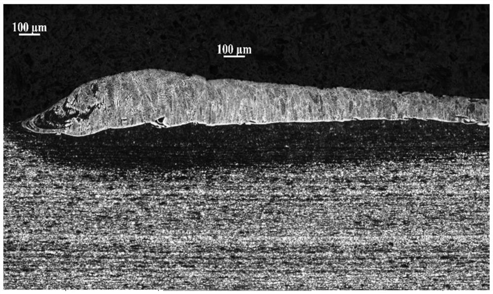
[0068] Step (3): Select the spot size of 2mm, and process the upper surface of the butt weld edge, the laser power is 3kW, the welding speed is 5m / min, the oscillation frequency is 30Hz, there is no shielding gas, and the surface structure is shown in the attached picture figure 1 ;

[0069] Step (4): Select the spot size of 0.7mm, and weld the processed test plate to be welded, the laser power is 2kW, no swing, and the welding speed is 3.5m / min;

[0070] Step (5): The ...

Embodiment 2

[0073] In this embodiment, the aluminum-silicon-coated high-strength hot-formed steel variable spot galvanometer scanning laser patch welding method includes the following steps:

[0074] Step (1): Select high-strength hot-formed steel with aluminum-silicon coating with a thickness of 1.5mm and high-strength hot-formed steel with aluminum-silicon coating with a thickness of 0.8mm, and degrease with alcohol; the thickness of the coating is 25-35 μm;

[0075] Step (2): Place the two steel plates on the workbench in an overlapping manner, and fix them with a special welding fixture to keep the overlapping gap at zero;

[0076] Step (3): Select the spot size to be 1mm, and perform initial welding on the welding area on the surface of the lap welding plate, with laser power of 3kW, swing amplitude of 0.5mm, swing frequency of 50Hz, welding speed of 6m / min, and no shielding gas. The depth of penetration is controlled to just reach the lower surface, and at this time, the upper surfa...


PUM

PropertyMeasurementUnit
thicknessaaaaaaaaaa
thicknessaaaaaaaaaa
tensile strengthaaaaaaaaaa

Abstract

The invention provides a galvanometer scanning laser welding method based on variable light spots. The galvanometer scanning laser welding method comprises the following steps of fixing two to-be-welded hot forming steel materials in a splicing or overlapping manner, so that the two hot forming steel materials are in close contact; and galvanometer scanning laser welding on a fixed position to be welded, and the position to be welded is melted and solidified to form a welding seam by adjusting the size of a light spot and setting a galvanometer scanning track. Good connection of hot forming steel is achieved, the mechanical property of a welding joint is improved, the proportion of high-temperature ferrite of a welding seam is reduced, the mechanical property of the welding joint is improved, and the problems that in the prior art, equipment cost is increased, alloy components are changed, production efficiency is reduced, production cost is improved, and quality is unstable are solved.

Description

technical field [0001] The invention relates to the field of welding technology, in particular to a laser welding method based on a variable light spot scanning mirror scanning. Background technique [0002] In order to realize the lightweight of automobiles, ultra-high-strength steel is being widely used in domestic and foreign automobile manufacturing. It has obvious advantages in anti-collision performance, processing technology and cost, and can meet the dual needs of reducing automobile weight and improving collision safety performance. . Ultra-high-strength steel is mainly used in the outer panels of the body, the inner panels of the body, the outer panels and reinforcement plates of the bumper, and various impact-resistant structural parts. [0003] As a typical ultra-high-strength automotive steel, hot-formed steel plate has extremely high strength and ductility. The tensile strength of the thermoformed steel plate is 500-800MPa before heating, and the elongation i...

Claims


Application Information

Patent Timeline
Patent Type & Authority Applications(China)
IPC IPC(8): B23K26/21B23K26/70B23K26/073B23K26/082
CPCB23K26/21B23K26/702B23K26/073B23K26/082B23K26/046
Inventor 林文虎张振波
Owner SHANGHAI TECH UNIV
Why Eureka
Try Eureka