Environment-friendly boiler waste heat recovery device for heat recovery based on heat layering

A heat recovery and recovery device technology, which is applied in the direction of reducing greenhouse gases, solid fuel combustion, lighting and heating equipment, etc., can solve the problems that boiler heat cannot be effectively used, consumes more fuel, and takes a long time to boil water, etc., to achieve Improve resource utilization, speed up heat transfer reaction, and avoid overheating effects

Inactive Publication Date: 2021-12-07
吕连婷
View PDF0 Cites 2 Cited by
  • Summary
  • Abstract
  • Description
  • Claims
  • Application Information

AI Technical Summary

Problems solved by technology

For example, when some small and medium-sized boilers use low-quality fuel for thermal combustion, the incomplete combustion of the fuel will produce more harmful gases, and the exhaust gas after combustion will convert SO2, SO3 and NO-X carried in the flue gas into condensation. The acid is hidden in the white smoke, and when it accumulates over time, it can form acid rain; and more than 10% of the heat energy is discharged into the atmosphere through the flue gas after combustion, so that the heat in the boiler cannot be used effectively, resulting in energy waste. At the same time, the boiler When boiling water, because the water is not preheated, it takes a long time to boil water, consumes more fuel, and wastes resources

Method used


Image

  • Environment-friendly boiler waste heat recovery device for heat recovery based on heat layering
  • Environment-friendly boiler waste heat recovery device for heat recovery based on heat layering
  • Environment-friendly boiler waste heat recovery device for heat recovery based on heat layering

Examples


Embodiment 1

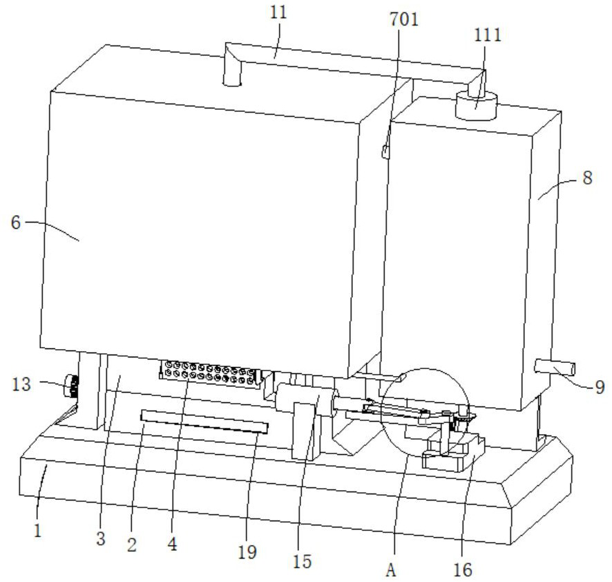
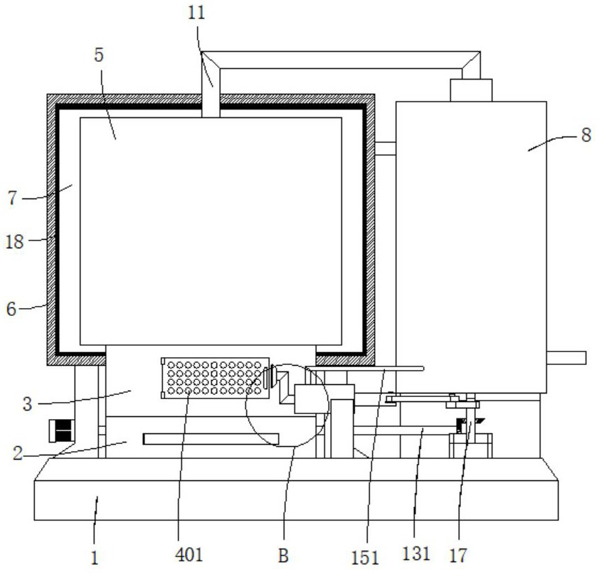
[0037] refer to Figure 1-3, an environmentally friendly boiler residual temperature recovery device based on heat recovery based on heat stratification, including a base 1, the top of the base 1 is connected to a slag chamber 2, the top of the slag chamber 2 is connected to a combustion chamber 3, and the outer wall of the combustion chamber 3 is provided with a fuel port. The outer wall of the fuel port is provided with a chamber door 4, and the outer wall of the chamber door 4 is dug with evenly distributed ventilation holes 401. The combustion chamber 3 is provided with a turning mechanism. The outer wall is covered with a casing 6, the first bracket is connected between the casing 6 and the base 1, the top outer wall of the combustion chamber 3 is provided with a smoke outlet for exhausting smoke, the combustion chamber 3, the heating water tank 5 and the casing 6 form a The smoke collection chamber 7 for absorbing smoke, the outer wall of the smoke collection chamber 7 i...

Embodiment 2

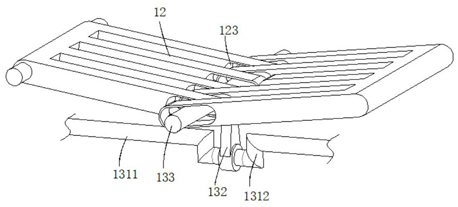
[0040] refer to Figure 3-4 , an environmentally friendly boiler waste temperature recovery device based on heat recovery based on heat stratification, which is basically the same as Embodiment 1. Further, the turning mechanism includes two placement plates 12 for placing fuel, and the two placement plates 12 pass through the The rotating shaft is rotatably connected to the inner walls on both sides of the combustion chamber 3, and the side where the placing plate 12 is away from the rotating shaft is dug with a chute 123. There is a drive shaft 131, and the end of the drive shaft 131 away from the drive motor 13 passes through the first bracket and the combustion chamber 3 in sequence and is movably connected with a swing rod 132, the outer wall of the swing rod 132 is connected with a connecting rod 133, and the connecting rod 133 is movably connected in the chute 123, and the connecting rod 133 is slidably connected to the inner wall of the combustion chamber 3.

[0041] F...

Embodiment 3

[0046] refer to figure 1 , figure 2 and Figure 5 , an environmentally friendly boiler waste temperature recovery device for heat recovery based on heat stratification, which is basically the same as Embodiment 2, and furthermore, the heat energy utilization mechanism includes a preheating water tank 8 connected to the smoke exhaust pipe 701, and the preheating water tank 8 is connected to the base 1 is connected with a second bracket, a water guide pipe 11 is connected between the preheating water tank 8 and the heating water tank 5, and the outer wall of the water guide pipe 11 is provided with a water pump 111, and the outer wall of the preheating water tank 8 is connected with a smoke outlet pipe 9 and a smoke outlet pipe 9 A preheating pipe 10 is connected to the smoke exhaust pipe 701, and the preheating pipe 10 is set as a serpentine pipe; after the smoke in the smoke collection chamber 7 enters the preheating water tank 8, the water body in the water tank is heat-exc...


PUM


Abstract

The invention discloses an environment-friendly boiler waste heat recovery device for heat recovery based on heat layering, and belongs to the technical field of heat recovery. The environment-friendly boiler waste heat recovery device for heat recovery based on heat layering comprises a base, wherein the top of the base is connected with a slag chamber, the top of the slag chamber is connected with a combustion chamber, a fuel port is formed in the outer wall of the combustion chamber, a chamber door is arranged on the outer wall of the fuel port, ventilation holes which are uniformly distributed are formed in the outer wall of the chamber door, a material turning mechanism is arranged in the combustion chamber, the end, far away from the slag chamber, of the combustion chamber is connected with a heating water tank, a shell sleeves the outer wall of the heating water tank, a first support is connected between the shell and the base, and a smoke outlet used for discharging smoke is formed in the outer wall of the top of the combustion chamber. According to the environment-friendly boiler waste heat recovery device, fuel can be completely combusted, so that harmful gas in the smoke generated after combustion is reduced, and environmental protection is facilitated; and meanwhile, the heat energy of the smoke after combustion is utilized, preheating is carried out before water body heating, so that the fuel consumption is reduced, the water boiling time is shortened, and the resource utilization rate is improved.

Description

technical field [0001] The invention relates to the technical field of heat recovery, in particular to an environmental protection boiler residual temperature recovery device for heat recovery based on heat stratification. Background technique [0002] Energy saving and emission reduction is an important theme of today's social development. While using resources and energy more efficiently, it is of great significance to coordinate the green development of the social economy and the environment. Boiler equipment is widely used in various fields of industry, agriculture and daily life. Improving boiler safety performance, operating efficiency and improving its energy saving characteristics is an important direction for the development of boiler equipment. Boilers that provide hot water are called hot water boilers and are mainly used for domestic purposes. [0003] However, the flue gas after fuel combustion has not been effectively treated and utilized. For example, when s...

Claims


Application Information

Patent Timeline
Patent Type & Authority Applications(China)
IPC IPC(8): F23B30/00F23J1/06F23J15/06
CPCF23B30/00F23J15/06F23J1/06Y02E20/30
Inventor 王浩
Owner 吕连婷
Why Eureka
Try Eureka