High-real-time motion control system and method

A motion control system, motion control technology, applied in general control systems, control/regulation systems, program control, etc., can solve problems affecting tracking accuracy, system dynamic performance constraints, long project cycle, etc., to improve tracking accuracy, solve Delay problems, the effect of complexity reduction

Active Publication Date: 2021-12-10
NANJING ZHONGKE ASTROMOMICAL INSTR
View PDF8 Cites 1 Cited by
  • Summary
  • Abstract
  • Description
  • Claims
  • Application Information

AI Technical Summary

Problems solved by technology

[0005] The above hardware architecture system has the following disadvantages: (1) The timing accuracy of the computer is low, and it takes a relatively long time to call the function development kits of various boards, which has a certain impact on the real-time performance of the system; (2) the boards Or the price of the servo controller is relatively expensive; (3) The internal hardware schematic diagram of the system, the core control algorithm and its internal parameters cannot be obtained, it is difficult to improve and optimize the system in the later stage, and the dynamic performance of the system is restricted; (4) Mature servo control The device does not necessarily have a high-precision clock counter; (5) The development is relatively difficult and the project cycle is long
[0006] It is very important to obtain the actual position in real time during the tracking process. The position of the encoder acquired by the traditional data acquisition card is not real-time. The reason is that it takes a certain amount of time to call the development kit function of the board, and this time may not be fixed. , In addition, the compatibility of the data acquisition card is not good, limited by the operating system, it will affect the final tracking accuracy to a certain extent
In addition, some technical solutions need to rely on foreign servo controllers. Although the real-time position can be obtained through the bus in real time, it has certain limitations, which is not conducive to product development, and the price is also very expensive.
[0007] At present, there is no fundamental solution to the time lag problem of the astronomical telescope control system. It can only be solved by improving the real-time performance of communication and operating system.

Method used


Image

  • High-real-time motion control system and method
  • High-real-time motion control system and method
  • High-real-time motion control system and method

Examples


Embodiment Construction

[0038] The present invention will be described in further detail below in conjunction with the accompanying drawings.

[0039] The present invention is a high real-time motion control system and method proposed aiming at the time-lag problem of the existing control system, therefore, the system and method of the present invention can be used to solve the time-lag problem of any control system. However, in order to illustrate the principle and structure of the present invention in detail, the following embodiments only use the telescope satellite pointing and tracking control as an example to describe in detail.

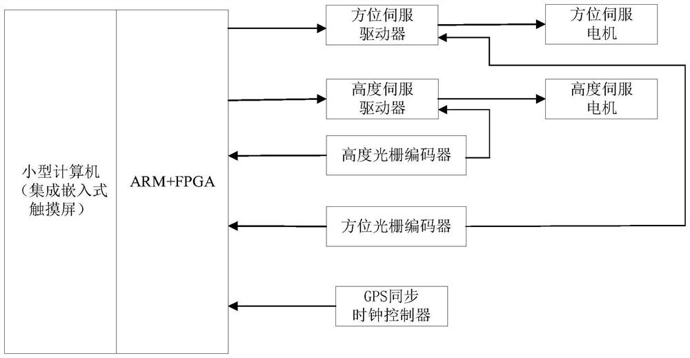
[0040] The high real-time motion control system of this embodiment is as figure 1 As shown, the system is a servo motion control scheme based on ARM and FPGA, mainly including: a small computer (in this embodiment, the small computer has an embedded touch screen with an operating system), a servo control system composed of ARM+FPGA Hardware architecture, azimuth serv...


PUM


Abstract

The invention discloses a high-real-time motion control system and method. The system comprises an ARM module, an FPGA module and a high-performance synchronous receiving module, wherein the FPGA module serves as a peripheral of the ARM module and is connected to an FMC high-speed bus; the high-performance synchronous receiving module is used for providing accurate second pulse synchronizing signals, the second pulse synchronizing signals are connected with an external interruption port of the ARM module, the ARM module receives the second pulse synchronizing signals, high-precision time is obtained through a software implementation method, and control system time is fed back to an upper computer. The upper computer compares the feedback time with the reference time of the upper computer until the synchronization is completed. The method effectively solves the time delay problem of an existing control system, and compared with the prior art, the complexity of the system is simplified, the cost of the control system is reduced, the tracking precision of control is improved, and the method is simple to operate and easy to implement.

Description

technical field [0001] The invention relates to the field of motion control, in particular to a high real-time motion control system and method, which are especially suitable for telescope satellite pointing and tracking control. Background technique [0002] The time-lag problem is a problem in many control systems, and the time-lag will reduce the performance of the control system and even affect the stability of the system. For astronomical telescopes, different control systems have different time lag problems. [0003] Astronomical telescopes track celestial bodies and artificial satellites, which require relatively high time accuracy. If the azimuth axis tracking speed is 4° / s, the time error is 1ms, and the azimuth axis pointing error is 14.4". With the change of tracking speed , due to the existence of time error, the tracking accuracy itself will be greatly affected; in addition, the lag in reading the actual position of the two-axis encoder will also seriously affe...

Claims


Application Information

Patent Timeline
Patent Type & Authority Applications(China)
IPC IPC(8): G05B19/042
CPCG05B19/0423G05B2219/25257Y02P90/02
Inventor 赵金标周小军朱庆生
Owner NANJING ZHONGKE ASTROMOMICAL INSTR
Why Eureka
Try Eureka