Inductor manufacturing method

A manufacturing method and inductor technology, which is applied in the manufacture of inductors/transformers/magnets, circuits, electrical components, etc., can solve problems such as heating of inductor products and increased inductance loss, reduce heat loss, reduce magnetic loss, and improve manufacturing yield Effect

Pending Publication Date: 2021-12-14
HENGDIAN GRP DMEGC MAGNETICS CO LTD
View PDF3 Cites 0 Cited by
  • Summary
  • Abstract
  • Description
  • Claims
  • Application Information

AI Technical Summary

Problems solved by technology

The injection-type inductors produced by the above method are generally used in circuits with lower frequency requirements of 100KHz, but with the advancement of 5G technology, power supply circuits and signal processing unit modules require inductors with higher frequencies, and the frequency is generally 500Khz and above. As the frequency rises, the magnetic loss, copper loss, eddy current loss and other losses of the inductor increase, and the inductance product has obvious heating problems. Based on the high-end application requirements of the product, consumer electronics products urgently need high-frequency, low-loss, and high-efficiency products.

Method used


Image

  • Inductor manufacturing method
  • Inductor manufacturing method
  • Inductor manufacturing method

Examples


Embodiment Construction

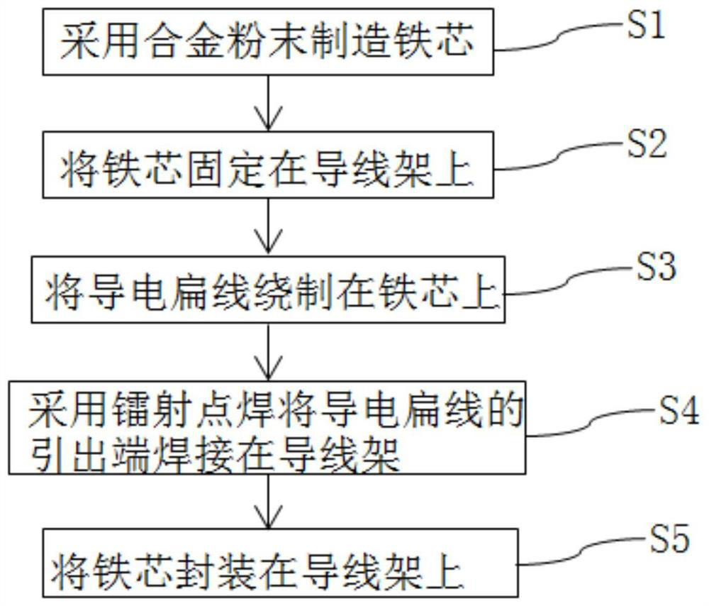
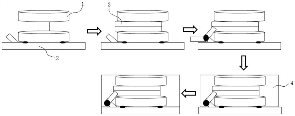
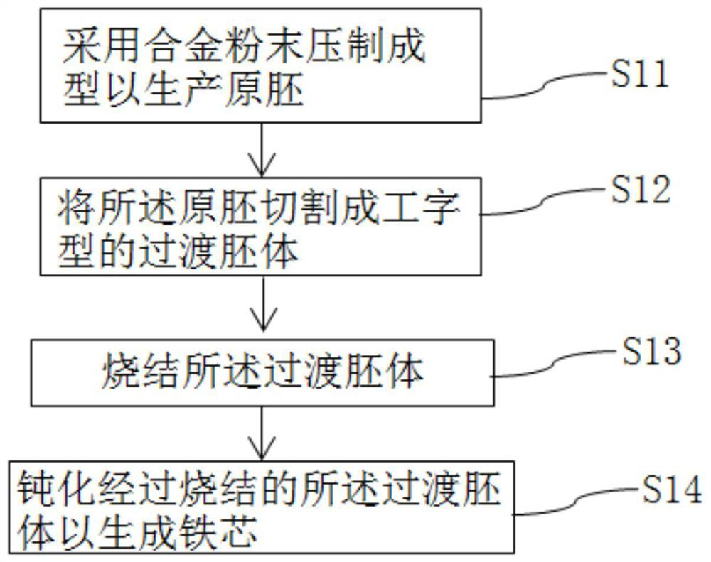
[0041] In order to make the technical problems solved by the present invention, the technical solutions adopted and the technical effects achieved clearer, the technical solutions of the present invention will be further described below in conjunction with the accompanying drawings and through specific implementation methods.

[0042] In describing the present invention, it is to be understood that the terms "center", "longitudinal", "transverse", "length", "width", "thickness", "upper", "lower", "front", " Back", "Left", "Right", "Vertical", "Horizontal", "Top", "Bottom", "Inner", "Outer", "Clockwise", "Counterclockwise", "Axial" , "radial", "circumferential" and other indicated orientations or positional relationships are based on the orientations or positional relationships shown in the drawings, and are only for the convenience of describing the present invention and simplifying the description, rather than indicating or implying the referred device or Elements must have c...


PUM

PropertyMeasurementUnit
thermal resistanceaaaaaaaaaa

Abstract

The invention discloses an inductor manufacturing method. The method comprises the following steps: manufacturing an iron core by adopting alloy powder, fixing the iron core on a lead frame, winding a conductive flat wire on the iron core, welding a leading-out end of the conductive flat wire on the lead frame by adopting laser spot welding, and packaging the iron core on the lead frame. According to an inductor manufactured by the inductor manufacturing method, copper loss and magnetic loss can be reduced, loss heating of a product under high-frequency use is reduced, and the requirement of a high-frequency use environment can be met.

Description

technical field [0001] The invention relates to a processing method for electrical components, in particular to an inductor manufacturing method. Background technique [0002] At present, many manufacturers' injection-type inductors have a winding body surrounded by powder coating. The winding body is made of prototype enamelled copper wire for coil winding, and the powder is surrounded by high-pressure molding or potting colloid, and then baked ( The peak baking temperature is 140-180°C) to heat-cure the glue to form an inductive product with a certain strength. The injection-type inductors produced by the above method are generally used in circuits with lower frequency requirements of 100KHz, but with the advancement of 5G technology, power supply circuits and signal processing unit modules require inductors with higher frequencies, and the frequency is generally 500Khz and above. As the frequency increases, the magnetic loss, copper loss, eddy current loss and other loss...

Claims


Application Information

Patent Timeline
Patent Type & Authority Applications(China)
IPC IPC(8): H01F41/00H01F41/02
CPCH01F41/00H01F41/02H01F41/0246
Inventor 张瑞平刘伟斌娄海飞
Owner HENGDIAN GRP DMEGC MAGNETICS CO LTD
Why Eureka
Try Eureka