Jerk and strong magnetic control method of synchronous electric spindle for ultra-high-speed grinding with variable load

An ultra-high-speed grinding and control method technology, which is applied in the direction of electronic commutation motor control, motor generator control, control system, etc., can solve the problem of the weakening of the electromagnetic torque of the permanent magnet flux linkage, the difficulty in the speed reaching the working speed, and the dynamics of the motor torque slow response

Active Publication Date: 2018-05-01
HUNAN UNIV
View PDF6 Cites 0 Cited by
  • Summary
  • Abstract
  • Description
  • Claims
  • Application Information

AI Technical Summary

Problems solved by technology

[0004] Using the existing maximum torque current ratio MTPA (Maximum Torque per Ampere, MTPA) or i d =0 Problems in the control method: (1) constant power expansion is difficult
When the rated speed of the motor is lower than the working speed, MTPA control is used for constant power speed regulation, because i d = 0, the armature does not produce negative magnetic field to offset the permanent magnet flux linkage, the air gap flux is constant, and the back electromotive force is proportional to the speed, which can easily cause the back electromotive force to be too large, exceeding the voltage limit that the driver can withstand, thus causing the driver Automatic alarm trip, the speed is difficult to reach the working speed required for ultra-high-speed grinding
(2) No reluctance torque, limited output
because i d = 0, the electromagnetic torque of the motor is only generated by the permanent magnet flux linkage without the reluctance torque item, resulting in the restriction of the output torque capability, and it is difficult to resist variable load ultra-high speed grinding
Moreover, the rated point of the motor is set at the working point, so there is no need for constant power control and speed regulation, only MTPA or constant torque control speed regulation is required, and the speed can be raised to the working speed required by ultra-high-speed grinding. However, due to the motor rated The speed is greatly increased, and the volume will be greatly reduced under the same rated power. The space of the motor is limited, and the rigidity of the shaft system is difficult to guarantee, which will inevitably affect the grinding accuracy.
[0005] Existing problems in adopting the existing field weakening control: (1) The torque characteristic of the motor is reduced, and the output is limited
High-speed magnetic field weakening leads to a decrease in the torque characteristics of the motor
On the one hand, in the state of high-speed rotation, the mechanical electromagnetic loss of the motor consumes part of the power; on the other hand, the weakening of the magnetic field makes the electromagnetic torque generated by the permanent magnet flux linkage gradually weakened.
Due to the decrease of motor torque characteristics and limited output, it is difficult to adapt to the needs of ultra-high-speed grinding conditions with variable loads
(2) Slow dynamic response of motor torque
Due to the hard torque characteristics of the motor, coupled with the coupling effect of motor parameter changes and system parameters, the torque dynamic response is slow and the tracking ability is lacking, which will inevitably affect the stability of the torque speed
(3) The motor current is large, which may easily cause the controller to saturate and stall synchronously with the motor
In view of the above reasons, the use of magnetic field weakening control has the limitation that it is difficult to balance grinding efficiency, grinding quality and grinding accuracy at the same time.

Method used


Image

  • Jerk and strong magnetic control method of synchronous electric spindle for ultra-high-speed grinding with variable load
  • Jerk and strong magnetic control method of synchronous electric spindle for ultra-high-speed grinding with variable load
  • Jerk and strong magnetic control method of synchronous electric spindle for ultra-high-speed grinding with variable load

Examples


Embodiment Construction

[0043] In the following, the speed regulation of the synchronous electric spindle facing variable load ultra-high speed grinding will be added on the basis of the traditional constant magnetism (MTPA) control method + "field weakening" control method to increase the synchronous electric spindle oriented to variable load ultra-high speed grinding of the present invention Taking the jerk and strong magnetic control ("strong magnetic" control method) as an example, the jerk and strong magnetic control method of the synchronous electric spindle oriented to variable load ultra-high speed grinding of the present invention will be further described in detail.

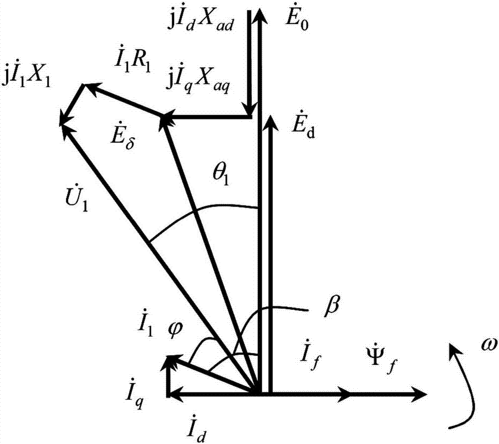
[0044] The jerk control of the permanent magnet synchronous electric spindle is actually the reverse control process of the weak field control. To clarify the "strong magnetic field" control principle, we must first understand the "weak magnetic field" control principle, the principle can be found in figure 1 ,in, is the eff...


PUM


Abstract

The invention discloses a synchronous electric spindle acceleration and strong magnetic control method oriented to variable load ultra-high-speed grinding. The expected command value of each phase voltage in the phase static coordinate system; the error signal between the expected command value of each phase voltage and the actual value of each phase voltage in the three-phase static coordinate system is used as the control signal of the power switch IGBT of each phase to each phase of the PWM Inverter driver The actual output current is vector controlled, and the expected command value of the q-axis current is continuously increased and the expected command value of the d-axis current is decreased, so that the internal power factor angle β of the motor is continuously reduced. The invention has good motor torque characteristics, high grinding efficiency, fast dynamic response of motor torque speed, good control robustness, high grinding quality and grinding precision, small motor current, and can effectively prevent controller saturation and motor synchronous stalling and The advantages of runaway, high efficiency and energy saving.

Description

technical field [0001] The invention relates to ultra-high-speed grinding processing technology, in particular to a method for controlling the jerk, acceleration, and intensity of a synchronous electric spindle facing variable-load ultra-high-speed grinding. Background technique [0002] Ultra-high-speed grinding is an extremely challenging high-efficiency precision machining technology in the field of advanced manufacturing. It is the focus and frontier of the world's equipment manufacturing industry and industrialization competition. It is used in high-end strategic equipment for modern military defense, such as the core of non-circular contours of ship engines. It has a wide range of applications in the high-efficiency grinding of parts. [0003] Variable load ultra-high-speed grinding is a normal state of machining. For example, during the grinding process of non-circular contour parts, the grinding load changes continuously with the workpiece rotation angle. In order t...

Claims


Application Information

Patent Timeline
Patent Type & Authority Patents(China)
IPC IPC(8): H02P21/16
Inventor 吕浪熊万里
Owner HUNAN UNIV
Why Eureka
Try Eureka