Spray cooling device for condensation of phase-change material assisted gas-phase working medium

A phase change material, spray cooling technology, applied in the direction of cooling/ventilation/heating transformation, electrical components, electrical equipment structural parts, etc., can solve problems such as heat dissipation deterioration, reduce back pressure, enhance heat transfer effect, and enhance utilization The effect of efficiency

Active Publication Date: 2021-12-14
UNIV OF SCI & TECH OF CHINA
View PDF4 Cites 0 Cited by
  • Summary
  • Abstract
  • Description
  • Claims
  • Application Information

AI Technical Summary

Problems solved by technology

[0004] In order to effectively reduce the pressure in the spray chamber and solve the deterioration of heat dissipation caused by the increase of vapor pressure during the cooling process, the present invention provides a spray cooling device that uses phase change materials to assist the condensation of working medium steam

Method used


Image

  • Spray cooling device for condensation of phase-change material assisted gas-phase working medium
  • Spray cooling device for condensation of phase-change material assisted gas-phase working medium
  • Spray cooling device for condensation of phase-change material assisted gas-phase working medium

Examples


Embodiment 1

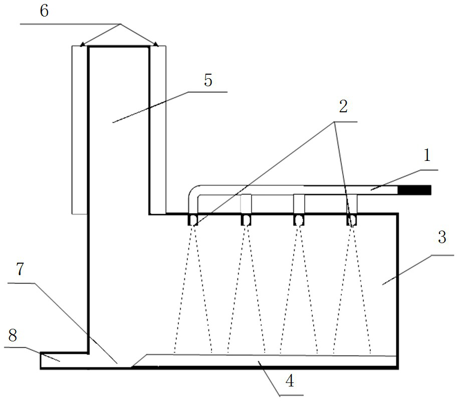
[0026] See figure 2 , A condensed spray cooling apparatus a phase change material includes a spray assisted vapor working chamber 3, the outer top of the spray chamber 3 is mounted on the two rows of inlet tube 1 through the branch pipes are each equipped with Bouin 1, two rows of nozzle inlet pipe array 2, the spray nozzle array 2 located at the top of cavity 3. 4 is attached to the thermal diffusion plate, and the heat diffusion plate 4 adjacent to the floor at the edge of the spray chamber 3 is provided with a concave shape as a sump on the bottom plate 7 of the spraying chamber 3, a spray chamber 7 side 3 side of the sump Bouin walls are provided with three or more liquid discharge pipe 8.

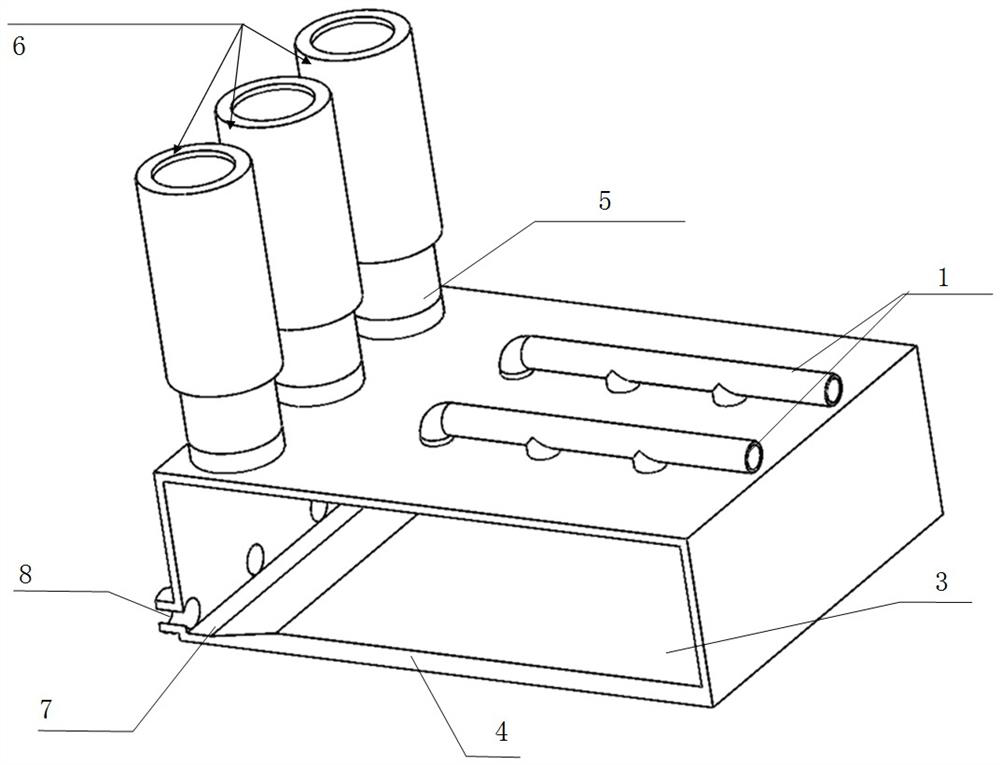
[0027] See figure 2 , 7 above the top of the spray sump chamber 3 are mounted side by side three cylindrical tubular condensation chamber 5. See figure 1 , The upper end of each condensation chamber 5 of the cylindrical tube is closed, the lower end of the spray chamber is connected by a s...

Embodiment 2

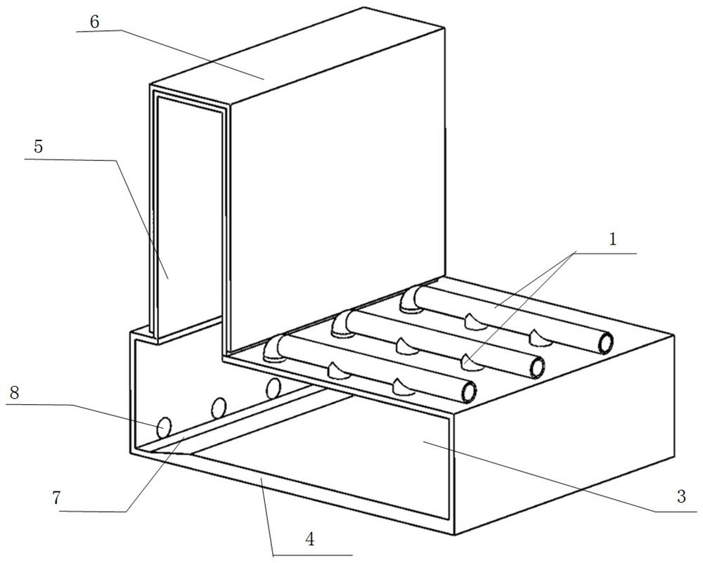
[0033] See image 3 , Condensation chamber 5 cuboidal housing, the housing top surface and four side surfaces are wrapped with a phase change material 6. The outer top of the spray chamber 1 3 is mounted on the branch pipe are respectively provided with a nozzle array of three rows of Bouin liquid inlet pipe 1, three rows of inlet tube 2, the spray nozzle array 2 located at the top of cavity 3. Other structures in Example 1.

[0034] Spray chamber cuboidal metal shell 3 has a size of 400 × 200 × 100 (mm), wall thickness is 5mm, the top nozzle array 3 to a spray chamber 2 8 × 3 arrangement, the spacing between adjacent nozzles is 30mm.

[0035] 5 material in the condensation chamber 2 This example aluminum alloy, box dimensions: height 150mm, length and width are 350mm, 80mm, a wall thickness of 5mm. 3 is connected to the interface on top of the rectangular spray chamber. The thickness of the outer surface of the phase change material wrapped condensation chamber 5 is 5mm, to provid...


PUM


Abstract

The invention provides a spray cooling device for condensation of a phase-change material assisted gas-phase working medium, and belongs to the technical field of refrigeration. The device comprises a spraying cavity, two or more rows of liquid inlet pipes are arranged on the outer side of the top of the spraying cavity, and a nozzle array is evenly distributed on each liquid inlet pipe; a heat diffusion bottom plate, a liquid collecting tank and a liquid discharging pipe are arranged on a bottom plate of the spraying cavity, and the improvement is that more than one condensation cavity is arranged at the top of the spraying cavity above the liquid collecting tank, and the condensation cavity is wrapped with a phase change material; the condensation cavity with the phase change material assists in reducing the pressure in the spraying cavity by 30%-36%, so that the saturated steam temperature of the spraying working medium is reduced by 10-15 DEG C. The phase change temperature and phase change latent heat characteristics of the phase change material are utilized, working medium steam is liquefied in the condensation cavity, the working pressure in the spray cavity is reduced, the evaporation rate in the spray cooling process is increased, the heat exchange effect of the spray cooling device is enhanced, and the spray cooling device has good practicability, is convenient to maintain in structure and has high durability.

Description

technical field [0001] The invention belongs to the technical field of refrigeration, and in particular relates to a spray cooling device which utilizes a phase-change energy storage material as an auxiliary. Background technique [0002] As a heat dissipation method with high-density heat flow processing capability, spray cooling has been used in metal smelting, server unit chip heat dissipation, laser technology and other applications with high heat generation power. The closed spray cooling is one of the heat dissipation devices that can recycle the cooling working fluid, and the heat source and the working fluid are non-contact. [0003] The structure of the existing closed spray cooling device generally includes: a cavity, a nozzle array, and a liquid discharge port. During operation, the exhaust condition of the working fluid in the spray chamber after evaporation will directly affect the spray cooling effect, and the spray The working medium vapor generated in the ch...

Claims


Application Information

Patent Timeline
Patent Type & Authority Applications(China)
IPC IPC(8): H05K7/20
CPCH05K7/20345H05K7/20318
Inventor 赵锐程文龙郑磊付豪潘宇晖陈健
Owner UNIV OF SCI & TECH OF CHINA
Why Eureka
Try Eureka