

Dynamic simulation test device and method for ultra-wideband radio fuze
A dynamic simulation and testing device technology, applied in fuzes, offensive equipment, weapon accessories, etc., can solve the problems of not covering performance indicators, difficult to obtain measured values, complex systems, etc., to achieve rapid and automatic calculation of blast height, improve test efficiency and , deploy simple effects
- Summary
- Abstract
- Description
- Claims
- Application Information
AI Technical Summary
Problems solved by technology
Method used
Image

Examples
Embodiment 1
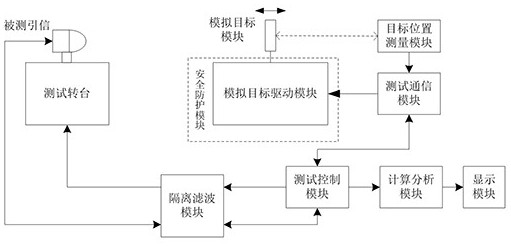
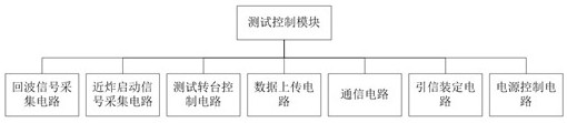
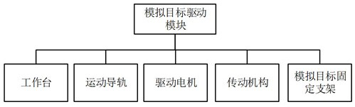
[0042] Such as Figure 4As shown, it is an ultra-wideband radio fuze dynamic simulation test device, including a test control module, a motor slide rail module and its controller, a corner reflector, a laser ranging module, an infrared communication module, a calculation and analysis module, a safety protection module, an isolation filter module, fuze test turntable, display module, the test control module is connected to the fuze test turntable in one direction through the isolation filter module, and is connected to the tested fuze in two directions, and the test control module is connected to the calculation and analysis module in one direction through the data line, The motor slide rail module and its controller are fixedly connected to the corner reflector through a mechanical structure, and the corner reflector reflects the echo signal when the electromagnetic wave of the fuze under test is irradiated, and the laser ranging module uses a real-time measurement corner refle...
Embodiment 2
[0059] Such as Figure 5 As shown, it is an ultra-wideband radio fuze dynamic simulation test device, including a test control module, a motor slide rail module and its controller, a metal plate, a resistive displacement sensor, a wireless communication module, a calculation and analysis module, a safety protection module, and an isolation filter module, a fuze test turntable, and a display module. The test control module is unidirectionally connected to the fuze test turntable through the isolation filter module, and is bidirectionally connected to the tested fuze. The test control module is unidirectionally connected to the calculation and analysis module through a data line. The motor slide rail module and its controller are fixedly connected to the metal plate through the mechanical structure. The metal plate reflects the echo signal when the electromagnetic wave of the fuze under test is irradiated. The resistive displacement sensor is installed on the slide rail to measur...
PUM
 Abstract
Description
Claims
Application Information