Light-emitting device, and electronic device and inspection method using same

A light-emitting device and light source technology, applied in the direction of optical elements used to change the spectral characteristics of emitted light, components of lighting devices, semiconductor devices of light-emitting elements, etc., can solve the problem of difficult to emit high-intensity fluorescence, short luminous life, etc. question

Pending Publication Date: 2021-12-21
PANASONIC INTELLECTUAL PROPERTY MANAGEMENT CO LTD
View PDF2 Cites 0 Cited by
  • Summary
  • Abstract
  • Description
  • Claims
  • Application Information

AI Technical Summary

Problems solved by technology

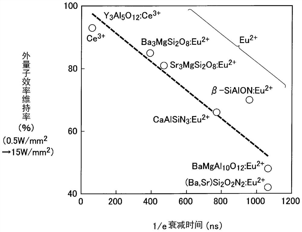
Therefore, conventionally, it has been considered that a phosphor having a longer luminescence lifetime is less likely to emit high-intensity fluorescence than a phosphor having a short luminescence lifetime.

Method used


Image

  • Light-emitting device, and electronic device and inspection method using same
  • Light-emitting device, and electronic device and inspection method using same
  • Light-emitting device, and electronic device and inspection method using same

Examples


Embodiment 1

[0156] Next, the light emitting device of this embodiment will be further described in detail through Example 1, but this embodiment is not limited thereto.

[0157] [Preparation of Phosphor]

Embodiment 1-1

[0159] The oxide phosphor used in Example 1-1 was synthesized using a production method utilizing a solid phase reaction. The phosphor of embodiment 1-1 is made of (Al 0.99 ,Cr 0.01 ) 2 o 3 The oxide phosphor represented by the composition formula. In addition, the phosphor of Example 1-1 is Cr 3+ Activate phosphors.

[0160] When synthesizing the oxide phosphor of Example 1-1, the following compound powders were used as main raw materials.

[0161] Aluminum oxide hydroxide (AlOOH): purity 2N5, manufactured by Kawai Lime Industry Co., Ltd.

[0162] Chromium oxide (Cr 2 o 3 ): Purity 3N, made by High Purity Chemical Research Institute Co., Ltd.

[0163] First, to become a stoichiometric compound (Al 0.99 ,Cr 0.01 ) 2 o 3 The above raw materials were weighed in the same way. Next, the weighed raw materials were put into a beaker filled with pure water, and stirred for 1 hour using a magnetic stirrer. Thereby, a slurry-like mixed raw material containing pure water ...

Embodiment 1-2

[0166] The oxide phosphor used in Example 1-2 was synthesized using a production method utilizing a solid phase reaction. The phosphor of embodiment 1-2 is made of Gd 3 (Ga 0.97 ,Cr 0.03 ) 5 o 12 The oxide phosphor represented by the composition formula. In addition, the phosphor of Example 1-2 is Cr 3+ Activate phosphors.

[0167] When synthesizing the oxide phosphor of Example 1-2, the following compound powders were used as main raw materials.

[0168] Gadolinium oxide (Gd 2 o 3 ): 3N purity, manufactured by Wako Pure Chemical Industries, Ltd.

[0169] Gallium oxide (Ga 2 o 3 ): 4N purity, manufactured by Wako Pure Chemical Industries, Ltd.

[0170] Chromium oxide (Cr 2 o 3 ): Purity 3N, made by High Purity Chemical Research Institute Co., Ltd.

[0171] First, to become the stoichiometric compound Gd 3 (Ga 0.97 ,Cr 0.03 ) 5 o 12 The above raw materials were weighed in the same way. Next, the weighed raw materials were put into a beaker filled with pure ...


PUM

PropertyMeasurementUnit
energyaaaaaaaaaa
fluorescence lifetimeaaaaaaaaaa
energyaaaaaaaaaa

Abstract

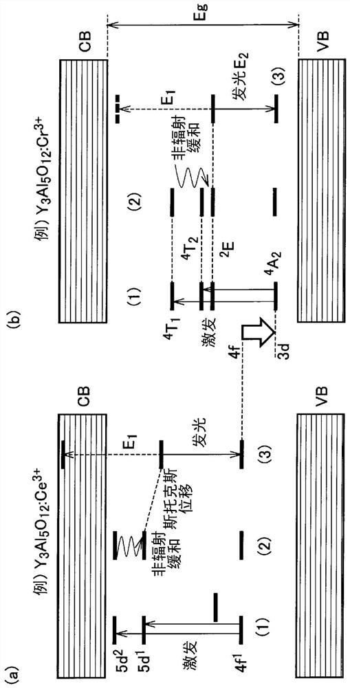
A light-emitting device (1, 1A, 1B, 1C) is provided with a light source (2) that emits a primary light (6) in which the light energy density exceeds 0.5 W / mm2, and a first fluorescent body (4) that absorbs the primary light and converts the primary light into a first wavelength-converted light (7) which has a longer wavelength than the primary light. A compound that is a parent compound for the first fluorescent body is a simple oxide in which there is one metal element or a composite oxide constituted by using a plurality of different types of the simple oxide as end members. A band-gap energy Eg of a crystal of the simple oxide is greater than the sum of E1 and E2, wherein the energy conversion value of the peak wavelength of the primary light is E1 electron volts and the energy conversion value of the fluorescent peak wavelength of the first wavelength-converted light is E2 electron volts. An electronic device of the present invention comprises the light-emitting device. An inspection method of the present invention uses the light-emitting device.

Description

technical field [0001] The present invention relates to a light-emitting device, electronic equipment using the light-emitting device, and an inspection method. Background technique [0002] Conventionally, there is known a light-emitting device that combines an excitation light source that emits laser light and a wavelength converter including a plurality of phosphors. As such a light emitting device having a light source that emits laser light, for example, a laser lighting device and a laser projector are known. Furthermore, in a light-emitting device having a light source for emitting laser light, high optical density excitation of phosphors is generally performed. [0003] In such a light-emitting device, generally, as the energy density of laser light from an excitation light source increases, the intensity (brightness) of light emitted from the phosphor tends to increase. However, when the energy density of laser light is higher than a predetermined value, it become...

Claims


Application Information

Patent Timeline
Patent Type & Authority Applications(China)
IPC IPC(8): H01L33/50H01S5/00C09K11/80G01N21/64G02B5/20F21V9/00F21V9/32F21V9/38F21V13/02F21Y115/10
CPCA61B1/07H01S5/0087H01S5/02251A61B1/0653A61B1/042A61B1/00188A61B1/00186A61B1/046A61B1/00066G02B23/2469G02B5/208H01L33/502H01L33/504C09K11/7766C09K11/685C09K11/7708C09K11/681
Inventor 新田充阿部岳志大盐祥三
Owner PANASONIC INTELLECTUAL PROPERTY MANAGEMENT CO LTD
Why Eureka
Try Eureka