Electric control silicone oil fan control system and method for wireless power supply and signal transmission

A wireless power supply and signal transmission technology, applied in the control of coolant flow, pump control, cooling of the engine, etc., can solve the problems of difficult fan wiring harness, difficult installation work, increased hardware cost, etc., to prevent pin short-circuit faults, eliminate Harness wear and effect of reducing power load

Inactive Publication Date: 2021-12-24
湖南行必达网联科技有限公司
View PDF4 Cites 1 Cited by
  • Summary
  • Abstract
  • Description
  • Claims
  • Application Information

AI Technical Summary

Problems solved by technology

The closed-loop control of the fan speed can be realized through this method of transmission, but the fixing of the fan harness is always difficult. In the after-sales failure, the fan harness often breaks or wears out, resulting in the failure of the speed sensor to feedback the speed, and the clutch and fan speed cannot be controlled. Therefore, the power supply wiring harness, sensor wiring harness and control wiring harness are prone to failures such as abnormal wear and tear during the use of the electronically controlled silicon oil fan clutch, and also lead to difficulties in installation work and increased hardware costs.

Method used


Image

  • Electric control silicone oil fan control system and method for wireless power supply and signal transmission
  • Electric control silicone oil fan control system and method for wireless power supply and signal transmission
  • Electric control silicone oil fan control system and method for wireless power supply and signal transmission

Examples


Embodiment Construction

[0031] In order to make the purpose, technical solutions and advantages of the present invention clearer, the technical solutions in the present invention will be clearly and completely described below in conjunction with the accompanying drawings in the present invention. Obviously, the described embodiments are part of the embodiments of the present invention , but not all examples. Based on the embodiments of the present invention, all other embodiments obtained by persons of ordinary skill in the art without creative efforts fall within the protection scope of the present invention.

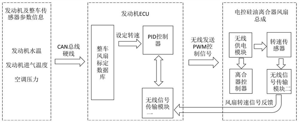
[0032] Because when the fan assembly of the electronically controlled silicon oil clutch is connected to the engine through the wire harness to realize power supply and control signal transmission, the fan wire harness is prone to breakage or wear in the narrow space of the electronically controlled silicon oil clutch, which will cause the speed sensor to fail to supply power and make the Clu...


PUM


Abstract

The invention provides an electric control silicone oil fan control system and method for wireless power supply and signal transmission. A wireless power supply device is additionally arranged on an electric control silicone oil fan driving shaft to supply power to a rotating speed sensor and a clutch controller on an electric control silicone oil fan clutch assembly; wireless signal transmission equipment is additionally arranged on the silicone oil fan clutch controller to achieve receiving and sending of rotating speed signals and clutch control signals; the wireless signal transmission equipment is additionally arranged at the ECU end of an engine to achieve receiving and sending of control signals and rotating speed signals, and therefore faults such as wire harness wear and connector water inflow are eradicated; meanwhile, energy recycling of fan shaft accessory work can be achieved, and the power supply load of the whole vehicle is reduced; wireless control is achieved through clutch signals, the clutch out-of-control situation caused by pin short circuit faults is prevented, and the system is more reliable and stable; and assembling is reduced, accessories such as wire harnesses and supports are omitted, and part cost is saved.

Description

technical field [0001] The invention relates to the field of engine fan control, in particular to an electronically controlled silicon oil fan control system and method for wireless power supply and signal transmission. Background technique [0002] The mechanical fan shaft is directly connected to the engine gear train, keeping the same speed as the engine crankshaft after the speed ratio, and does not require the participation of the control system, open-loop control; the silicone oil fan clutch is one of the key equipment commonly used for engine fan heat dissipation. The structure of the electronically controlled silicone oil fan clutch is similar to that of the silicone oil fan clutch. The difference is that the heat-sensitive bimetal temperature-sensing valve of the silicone oil fan clutch is replaced by an electromagnetic valve with an electromagnetic coil. According to the external conditions of the engine (water temperature, intake temperature, air conditioner, etc.)...

Claims


Application Information

Patent Timeline
Patent Type & Authority Applications(China)
IPC IPC(8): F01P7/04F04D27/00
CPCF01P7/042F04D27/004
Inventor 肖波罗小龙李翔宇
Owner 湖南行必达网联科技有限公司
Why Eureka
Try Eureka