Parasitic unit loaded high-gain dual-frequency microstrip antenna

A technology of parasitic unit and microstrip antenna, which is applied to antennas, antenna grounding devices, devices that enable antennas to work in different bands at the same time, and can solve the problem of increasing volume or cross-sectional area, limiting the usability of microstrip antennas, and The miniaturization development trend of the chip antenna does not match with other problems, so as to achieve the effect of improving performance parameters, saving area and small volume

Active Publication Date: 2021-12-24
CHANGSHA UNIVERSITY OF SCIENCE AND TECHNOLOGY
View PDF10 Cites 1 Cited by
  • Summary
  • Abstract
  • Description
  • Claims
  • Application Information

AI Technical Summary

Problems solved by technology

However, the above method increases the volume or cross-sectional area, which is inconsistent with the development trend of miniaturization and low profile of the microstrip patch antenna, and limits the usability of the microstrip antenna to a certain extent.

Method used


Image

  • Parasitic unit loaded high-gain dual-frequency microstrip antenna
  • Parasitic unit loaded high-gain dual-frequency microstrip antenna
  • Parasitic unit loaded high-gain dual-frequency microstrip antenna

Examples


Embodiment Construction

[0026] In order to make the purpose, technical solution and advantages of the present application clearer, the present application will be further described in detail below in conjunction with the accompanying drawings and embodiments. It should be understood that the specific embodiments described here are only used to explain the present application, and are not intended to limit the present application.

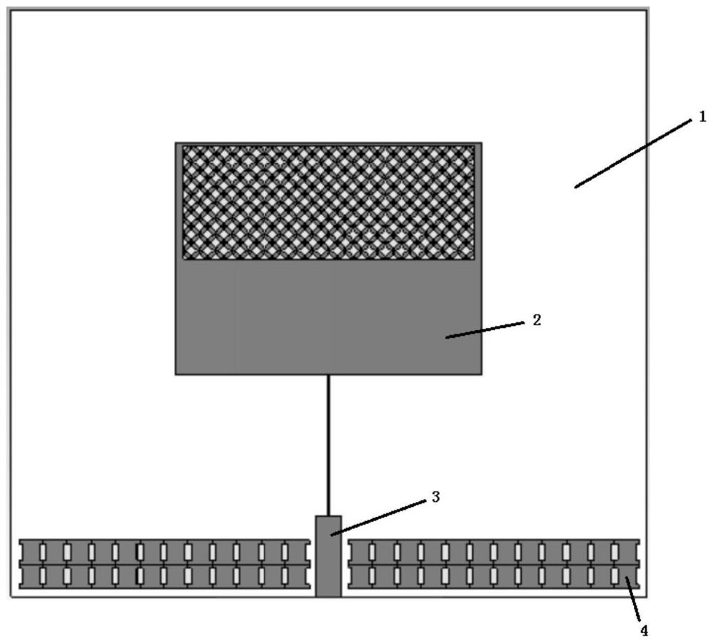
[0027] The present invention proposes a high-gain dual-band microstrip antenna loaded by a parasitic unit, such as figure 1 As shown, the antenna includes a metal floor layer, a dielectric substrate layer 1, a rectangular radiation patch 2, a feeder 3, and a parasitic unit 4; the metal floor layer is the bottom layer, and the dielectric substrate layer 1 covers the metal floor layer Above, the rectangular radiation patch 2 is located on the upper surface of the dielectric substrate layer 1, the feeder 3 is arranged on one side of the upper surface of the dielectric substra...


PUM

PropertyMeasurementUnit
thicknessaaaaaaaaaa
thicknessaaaaaaaaaa
Resonant frequencyaaaaaaaaaa

Abstract

The invention provides a parasitic unit loaded high-gain dual-frequency microstrip antenna. The antenna mainly comprises a metal floor layer, a dielectric substrate layer, a rectangular radiation patch, a feeder line and a parasitic unit, the metal floor layer is the bottommost layer, the dielectric substrate layer covers the metal floor layer, the rectangular radiation patch is located on the upper surface of the dielectric substrate layer, the microstrip feeder is arranged on one side of the upper surface of the dielectric substrate layer and connected with the rectangular radiation patch, and the parasitic units are arranged on the two sides of the feeder. The upper half part of the rectangular radiation patch is composed of a plurality of four-leaf clover-shaped arc-shaped patterns which are uniformly distributed; the structure of the parasitic unit is obtained by respectively setting a group of opposite sides of a square into a shape like a Chinese character 'ao'. According to the antenna, double-frequency resonance frequency points can be realized in an S wave band with a relatively small structure, the gain of the microstrip antenna is improved, and the practicability of the microstrip antenna is enhanced.

Description

technical field [0001] The present application relates to the technical field of antennas, in particular to a high-gain dual-band microstrip antenna loaded with parasitic elements. Background technique [0002] With the development of electronic technology in the fields of mobile communication, aerospace and other fields, all kinds of electronic equipment are developing towards the direction of miniaturization. Microstrip antennas are widely used in the fields of mobile communication, aerospace, electronic countermeasures and radar. Microstrip antennas have attracted widespread attention due to their small size, low profile, and easy integration with large-scale integrated circuits. However, its own structural characteristics lead to the disadvantages of low gain and poor directivity of the microstrip antenna. Moreover, due to the rapid development of antenna wireless systems, the original frequency bands are becoming more and more crowded. In order to increase the number...

Claims


Application Information

Patent Timeline
Patent Type & Authority Applications(China)
IPC IPC(8): H01Q1/36H01Q1/38H01Q1/48H01Q5/20H01Q13/08
CPCH01Q13/08H01Q5/20H01Q1/48H01Q1/38H01Q1/36Y02D30/70
Inventor 卞立安李延秀王垚琨黄元芯陈冉昊
Owner CHANGSHA UNIVERSITY OF SCIENCE AND TECHNOLOGY
Why Eureka
Try Eureka