Liquid crystal holographic phased-array antenna beam synthesis method for correcting reference wave model

A phased array antenna and integrated method technology, applied in the directions of antenna arrays, antennas, antenna arrays, etc., which are individually energized, can solve problems such as limited antenna beamforming performance, improve beam pointing accuracy, and avoid premature grating lobes , the effect of reducing side lobes

Pending Publication Date: 2021-12-28
UNIV OF ELECTRONIC SCI & TECH OF CHINA
View PDF0 Cites 0 Cited by
  • Summary
  • Abstract
  • Description
  • Claims
  • Application Information

AI Technical Summary

Problems solved by technology

[0006] The purpose of the present invention is to solve the problem that the inaccuracy of the reference wave model in the above-mentioned prior art leads to the limitation of the beamforming performance of the antenna, and to provide a liquid crystal holographic phased array antenna beam synthesis method for modifying the reference wave model. The scattering effect of the radiation unit on the guided wave corrects the reference wave model to improve the amplitude and phase accuracy of the unit excitation signal; the continuous adjustable characteristics of the liquid crystal material are used to introduce multi-bit quantization coding, so that the physically realized antenna array is closer to the theory Computed interference patterns that ultimately improve the beamforming and beamscanning performance of holographic antennas

Method used


Image

  • Liquid crystal holographic phased-array antenna beam synthesis method for correcting reference wave model
  • Liquid crystal holographic phased-array antenna beam synthesis method for correcting reference wave model
  • Liquid crystal holographic phased-array antenna beam synthesis method for correcting reference wave model

Examples


Embodiment 1

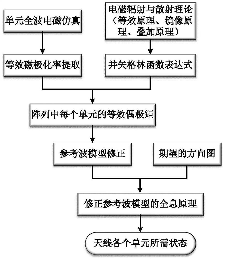
[0062] This embodiment provides a liquid crystal holographic phased array antenna beam synthesis method for modifying the reference wave model, and its flow chart is as follows figure 1 shown, including the following steps:

[0063] Step 1. Cell polarizability extraction

[0064] Each sub-wavelength radiation unit in the liquid crystal holographic phased array antenna is equivalent to a magnetic dipole, and the entire liquid crystal holographic phased array antenna is equivalent to a coupled magnetic dipole array;

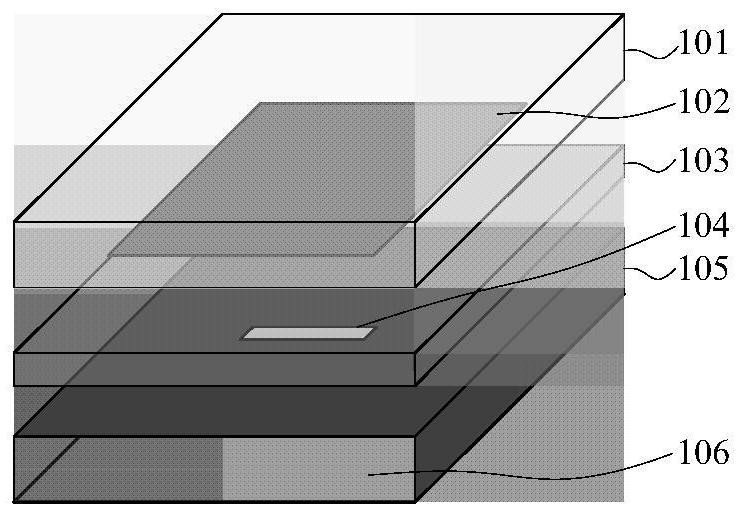
[0065] The liquid crystal holographic phased array antenna in this embodiment is a one-dimensional liquid crystal holographic phased array antenna based on rectangular waveguide feeding. The structural diagram of the radiation unit is as follows: figure 2 As shown, it includes a first dielectric plate 101, a radiation patch 102 located below the first dielectric plate 101, a second dielectric plate 103 located below the radiation patch 102, and a radiation patch ...

Embodiment 2

[0118] This embodiment provides a liquid crystal holographic phased array antenna beam synthesis method for modifying the reference wave model, and its flow chart is as follows figure 1 shown, including the following steps:

[0119] Step 1. Cell polarizability extraction

[0120] Each sub-wavelength radiation unit in the liquid crystal holographic phased array antenna is equivalent to a magnetic dipole, and the entire liquid crystal holographic phased array antenna is equivalent to a coupled magnetic dipole array;

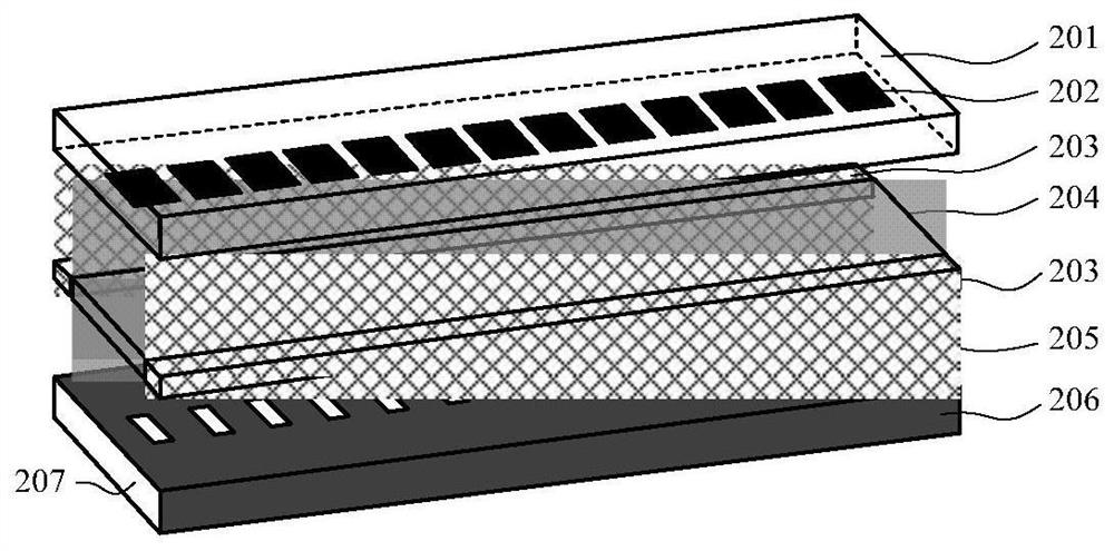
[0121] The liquid crystal holographic phased array antenna described in this embodiment is a two-dimensional liquid crystal holographic phased array antenna fed by a parallel plate waveguide. The structural diagram of the radiation unit is as follows Figure 4 As shown, it includes a dielectric plate 301 , a radiation patch 302 , a dielectric plate 303 , a metal plate 304 with a slit in the center, a dielectric plate 305 , a metal plate 306 , and a dipole antenna ...


PUM


Abstract

The invention discloses a liquid crystal holographic phased-array antenna beam synthesis method for correcting a reference wave model, and belongs to the technical field of holographic antennas. According to the method, based on the electromagnetic radiation and scattering theory, a high-precision electromagnetic model considering the scattering effect of each radiation unit on guided waves is established through a semi-analytical method, a reference wave model in the holographic principle is corrected, the amplitude and phase precision of excitation signals of each unit are improved, and finally the antenna beam forming performance is improved; the problem that an existing beam synthesis method based on the holographic principle is not high in precision is solved.

Description

technical field [0001] The invention belongs to the technical field of holographic antennas, and in particular relates to a liquid crystal holographic phased array antenna beam synthesis method for modifying a reference wave model. Background technique [0002] The current method to realize the holographic antenna is to apply the holographic principle in optics to the microwave band. The principle of holography originated from optics at the earliest. It is to interfere the reference light with the object light scattered by the object, and record the interference fringes. The interference fringes contain all the amplitude and phase information of the light scattered by the object. When the same reference light is used again When the interference fringe pattern is irradiated, a three-dimensional stereoscopic image of the object can be recovered. Since then, the idea of ​​holographic principle has been applied to the field of microwave antenna, and the concept of holographic a...

Claims


Application Information

Patent Timeline
IPC IPC(8): G06F30/20H01Q3/26H01Q3/28H01Q21/00H01Q21/06
CPCG06F30/20H01Q21/065H01Q21/0006H01Q3/26H01Q3/28
Inventor 梁锋刘子冰汪相如赵德双王秉中
Owner UNIV OF ELECTRONIC SCI & TECH OF CHINA
Why Eureka
Try Eureka