Unlock instant, AI-driven research and patent intelligence for your innovation.

Ventilation and radiation protection structure of concrete silo type spent fuel storage device

A storage device and radiation protection technology, applied in the third-generation passive nuclear power and nuclear power fields, can solve the problems that the dose rate level at the vent cannot meet the requirements, the high radiation level of the external environment, and the impact of radiation safety, etc., so as to ensure the ventilation capacity and process Ripening, Effects of Reduced Radiation Levels

Pending Publication Date: 2021-12-28
上海核工程研究设计院股份有限公司
View PDF0 Cites 0 Cited by
  • Summary
  • Abstract
  • Description
  • Claims
  • Application Information

AI Technical Summary

Problems solved by technology

The ventilation channel set up based on the coaxial line has poor shielding effect, so that the leakage beam of radioactive particles passing through the ventilation channel has a great impact on the external radiation safety of the storage device, and the dose rate level at the ventilation port is several times higher than that outside the main shielding body Above the order of magnitude
Especially for high-fuel and highly radioactive spent fuel assemblies, if the concrete silo-type spent fuel dry storage device still adopts the linear ventilation design of the prior art, or only a single short labyrinth design is arranged in the axial direction, the dose rate at the vent will The level is difficult to meet the requirements
For example, for the AP1000 or CAP1400 high-burnup spent fuel of the third-generation passive nuclear power plant, due to the strong radioactivity of the high-burnup spent fuel, the current design of the ventilation channel will make the dose level at the vent close to 10mSv / h, causing the external environment Radiation levels are too high

Method used


Image

  • Ventilation and radiation protection structure of concrete silo type spent fuel storage device
  • Ventilation and radiation protection structure of concrete silo type spent fuel storage device
  • Ventilation and radiation protection structure of concrete silo type spent fuel storage device

Examples


Embodiment

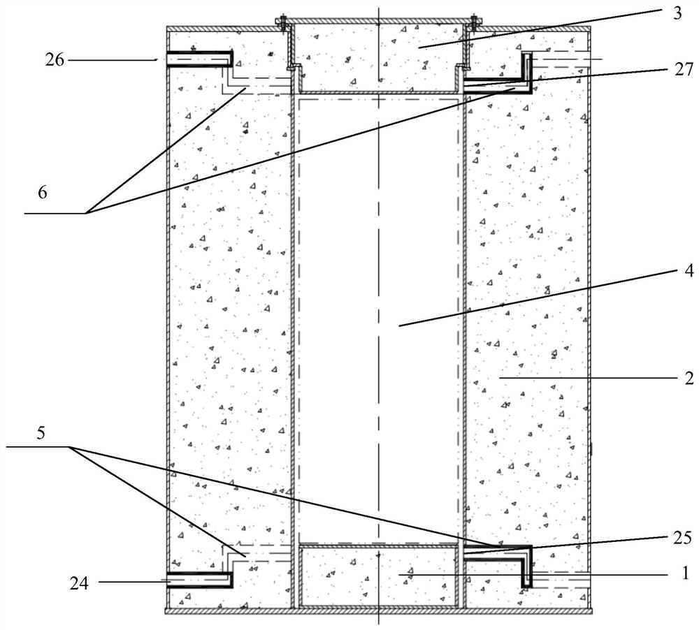
[0033] Such as figure 1 with Figure 5 As shown, the ventilation and radiation protection structure of a concrete silo-type spent fuel storage device in the present invention includes a concrete shielding system and a ventilation system. The concrete shielding system includes a base 1 , a side cylinder 2 and a top cover 3 . Among them, the main structures of the base 1, the side cylinder 2 and the top cover 3 are all made of concrete, and the outer surface of the concrete shield can be covered with carbon steel or stainless steel, or not.

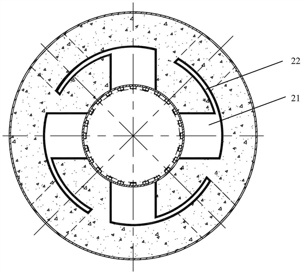
[0034] The side cylinder 2 is provided with a ventilation channel due to the demand for decay heat export.

[0035] In this embodiment, a certain air gap is provided between the base 1 and the side cylinder 2, and a part of the radioactive particles are guided to leak into the air gap, thereby reducing the level of leakage to the external environment through the ventilation channel.

[0036]In this embodiment, the ventilation system inclu...


PUM


Abstract

The invention belongs to the technical field of nuclear power, and particularly discloses a ventilation and radiation protection structure of a concrete silo type spent fuel storage device, which comprises a concrete shielding body and a ventilation system, wherein a ventilation flow channel adopts a labyrinth design, particularly an azimuth angle labyrinth is formed by an inner layer ventilation channel and an outer layer ventilation channel, and a shielding grid is mounted in the ventilation flow channel. According to the invention, the labyrinth type design of a ventilation flow channel greatly improves the radiation shielding effect, and on the basis of keeping the ventilation performance, a shielding grid improves the attenuation function of radioactive neutrons and photons, so that the irradiation level leaked to the external environment through the ventilation flow channel is reduced so as to reduce the irradiation dose received by workers in the operation and maintenance process; and the ventilation and radiation protection structure has the characteristics of good shielding effect, mature shielding material, low price, simple ventilation flow channel structure and convenience in construction.

Description

technical field [0001] The invention relates to the field of nuclear power technology, in particular to the field of third-generation passive nuclear power, and in particular to a ventilation and radiation protection structure for a concrete silo-type spent fuel storage device. Background technique [0002] The capacity of the fuel storage pool built into the nuclear power plant is limited, and generally can only meet the storage needs of the spent fuel discharged within more than ten years, while the design life of the nuclear power plant is 40-60 years. At present, many nuclear power plants in my country are already facing the problem of insufficient storage capacity of spent fuel pools in the plants. In the future, the amount of spent fuel produced in my country will continue to increase year by year. Dry storage of spent fuel is another temporary storage mode before the final disposal of spent fuel. At present, many nuclear power plants in my country have developed dry st...

Claims


Application Information

Patent Timeline
IPC IPC(8): G21C19/07G21F1/04G21D1/02
CPCG21C19/07G21F1/04G21D1/02Y02E30/00Y02E30/30
Inventor 王梦琪丁谦学梅其良黎辉翁晨阳郑征毛兰方史涛陈祖盼周岩夏春梅高静
Owner 上海核工程研究设计院股份有限公司