Wiring device of single-line slicing machine

A wiring device and slicer technology, applied in the direction of grinding drive device, fine working device, grinding machine tool parts, etc., can solve the problems of low cutting efficiency, high clamping degree of strip steel strip, high cost of processing materials, etc. , to achieve the effect of simplifying the overall structure, improving cutting efficiency, and convenient control and operation

Pending Publication Date: 2021-12-31
宁波新宁菱机械制造有限公司
View PDF0 Cites 0 Cited by
  • Summary
  • Abstract
  • Description
  • Claims
  • Application Information

AI Technical Summary

Problems solved by technology

[0004] 1. The original slicing machine was the outer garden slicing machine (including multi-knife slicing machine) that appeared in the 1850s. Due to the thicker blade, the processing effect was poor, and the cut material required secondary processing, resulting in High cost and high material waste rate;
[0005] 2. The saw-shaped multi-strip steel strip slicer, because it uses granular drills and frosted, leads to low cutting efficiency, and the strip-shaped steel strips are tightly clamped, which is difficult and labor-intensive;
[0006] 3. The Japanese slicer was introduced in the 1970s, and the processing effect and efficiency were greatly improved, but one operator can only operate 2-3 mach

Method used


Image

  • Wiring device of single-line slicing machine
  • Wiring device of single-line slicing machine
  • Wiring device of single-line slicing machine

Examples


Example Embodiment

[0033] Example 1:

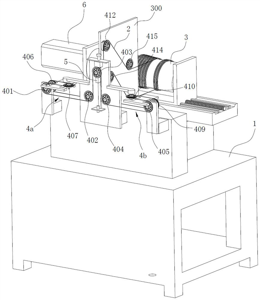
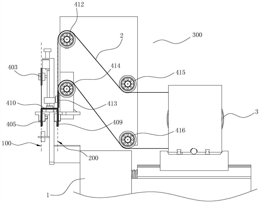
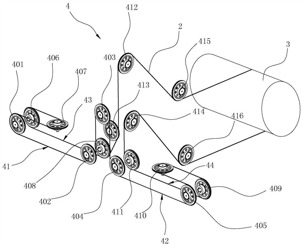
[0034] like Figure 1~4 As shown, the single wire slicer wiring device of this embodiment includes a cutting wire 2 and a guide wheel assembly 4 . Wherein, the cutting wire 2 is used for cutting materials, and the cutting wire 2 is wound on a drum 3. The cutting wire 2 in this embodiment adopts a diamond wire, but of course the cutting wire is not limited to a diamond wire. The drum 3 is rotatably arranged on the rear side of the frame 1, and the drum 3 is horizontally arranged left and right. The upper side of the drum 3 is the first winding side, and the lower side of the drum 3 is the second winding side, and the first winding side and the second winding side are in the same state as the winding state and the returning wire as the rotation direction of the drum 3 changes. Toggle between states. For example, when the drum 3 rotates in one direction, the upper side of the drum 3 is the line side of the cutting line 2, and the lower side of the drum 3 is...

Example Embodiment

[0045] Example 2:

[0046] The difference between this embodiment and Embodiment 1 lies in that the setting positions of the seventh guide wheel and the tenth guide wheel are different.

[0047] like Figure 5 As shown, the seventh guide wheel 407' is arranged above the first guide wheel 401 and the sixth guide wheel 406. Corresponding, its front edge corresponds to the outer edge of the first guide wheel 401; the tenth guide wheel 410' is located above the fifth guide wheel 405 and the ninth guide wheel 409, and the axis line of the tenth guide wheel 410' is arranged horizontally And its rear edge corresponds to the outer edge of the ninth guide wheel 409 , and its front edge corresponds to the outer edge of the fifth guide wheel 405 . The first end of the cutting line 2 is arranged around the outer edge of the first guide wheel 401, the upper edge of the seventh guide wheel 407', the outer edge of the sixth guide wheel 406, and the lower edge of the eighth guide wheel 408 ...


PUM


Abstract

The invention relates to a wiring device of a single-line slicing machine. The wiring device comprises a cutting line used for cutting materials and further comprises a guide wheel assembly, a roller is rotatably arranged on a rack and used for winding the cutting line, the upper side of the roller is a first winding side, the lower side of the roller is a second winding side, and the first winding side and the second winding side are switched between a winding displacement state and a line return state in a reciprocating manner along with switching of the rotating direction of the roller. The guide wheel assembly is rotatably arranged on the rack and used for guiding the direction of the cutting line, and the cutting line bypasses the guide wheel assembly to form at least two sets of cutting areas arranged at intervals. The winding structure for single-line cutting is provided, the cutting line is output from one side of the roller and withdrawn from the other side of the roller, reciprocating conveying of the cutting line is achieved through forward and reverse rotation of the roller, the guide wheel assembly guides the direction of the cutting line to divide different sections of the cutting line into different cutting areas, multiple materials can be cut at the same time, and the cutting efficiency is improved.

Description

technical field [0001] The invention relates to the technical field of single-wire cutting, in particular to a wiring device for a single-wire slicing machine. Background technique [0002] The materials processed by machine tools for parts involve two major fields, namely plastic materials and hard and brittle materials. Machine tools for plastic material processing are general-purpose machine tools for metal cutting and processing, with a wide range of machine performance; machine tools for processing hard and brittle material parts are special machine tools for diamond tool processing (except electric processing machine tools). It is a special machine tool for machining hard and brittle material parts with wire tools. [0003] The above-mentioned cutting range of machine tools with slicing function includes NdFeB magnetic materials, ferrite magnetic materials, ceramics, crystals, semiconductors, gemstones, quartz, glass, crystals, precious stones, hard alloys and other h...

Claims


Application Information

Patent Timeline
IPC IPC(8): B28D1/22B28D5/04B28D7/00B24B27/06B24B27/00B24B47/12
CPCB28D5/045B28D1/22B28D5/0064B28D7/005B24B27/0633B24B27/0023B24B47/12
Inventor 陈伟章
Owner 宁波新宁菱机械制造有限公司
Why Eureka
Try Eureka