Index gradient acoustic covering layer with embedded scatterers and cavities

Active Publication Date: 2021-12-31
JILIN UNIV
View PDF5 Cites 3 Cited by
  • Summary
  • Abstract
  • Description
  • Claims
  • Application Information

AI Technical Summary

Problems solved by technology

The document "Sound absorption by rubber coatings with periodic voids and hard inclusions" proposes a combination structure of hard inclusions and cavities that are periodically distributed inside the sound-absorbing layer, using dipole resonance related to hard inclusions and cavities Control sound absorption with Fabry-Perot resonance, and finally achieve an absorption peak at 500Hz, but the low-frequency absorption peak is single, and there is also the problem of narrow sound absorption frequency band

Method used


Image

  • Index gradient acoustic covering layer with embedded scatterers and cavities
  • Index gradient acoustic covering layer with embedded scatterers and cavities
  • Index gradient acoustic covering layer with embedded scatterers and cavities

Examples


Embodiment 1

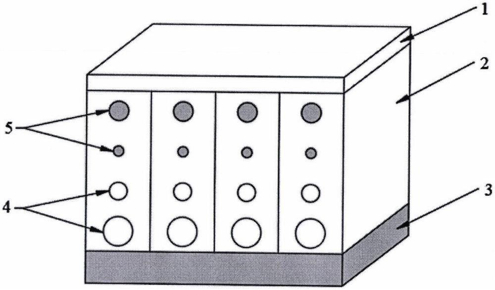
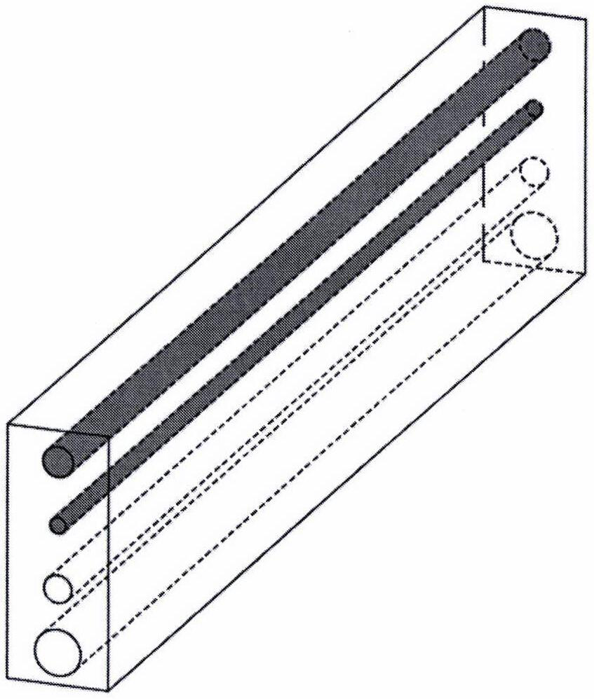
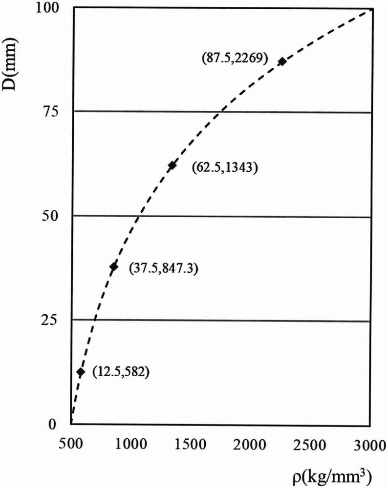
[0029] Each sound-absorbing layer unit is divided into 4 layers with equal thickness, and the layering method is as follows: image 3 As shown, the specific equivalent density is in image 3 Marked out. The equivalent densities of the four layers of media selected along the y-axis are 582kg / m3 、847.3kg / m 3 、1343kg / m 3 、2269kg / m 3 , the embedded structure radii to the 4-layer medium calculated by the homogenization method are 9.12mm (cavity), 5.51mm (cavity), 3.15mm (steel cylinder), 6.05mm (steel cylinder) from bottom to top. The distance between the center of the scatterer and the cavity in each unit is c=25mm, and the distance between the center of the scatterer on the first layer and the cavity on the fourth layer is d from the top and bottom 1 =12.5mm, distance from both ends is d 2 = 12.5 mm. Figure 5 The sound absorption coefficient curves of the gradient medium acoustic covering layer and the homogeneous medium acoustic covering layer of the present invention are...

Embodiment 2

[0031] Different from Example 1, in Example 2, the sound-absorbing layer is divided into 5 layers with equal thickness, and the layering method is the same as that in Example 1. The equivalent densities of the five layers of media selected along the y-axis are 564kg / m 3 、749.7kg / m 3 、1056.8kg / m 3 、1563kg / m 3 、2397.5kg / m 3 , the embedded structure radii to the 5-layer media calculated by the homogenization method are 8.33mm (cavity), 6.31mm (cavity), 1.15mm (steel cylinder), 3.61mm (steel cylinder), and 5.68mm (steel cylinder). The distance between the center of the scatterer and the cavity in each unit is c=20mm, and the distance between the center of the scatterer on the first layer and the cavity on the fourth layer is d from the top and bottom 1 =10mm, the distance between both ends is d 2 = 12.5 mm. Figure 5 The sound absorption coefficient curves of the gradient medium acoustic covering layer and the homogeneous medium acoustic covering layer of the present invent...


PUM

PropertyMeasurementUnit
densityaaaaaaaaaa
lengthaaaaaaaaaa
radiusaaaaaaaaaa

Abstract

The invention discloses an index gradient acoustic covering layer with embedded scatterers and cavities. The index gradient acoustic covering layer comprises a matching layer (1), a sound absorption layer (2) and a steel backing (3). The matching layer is made of glass fiber reinforced plastics, the sound absorption layer is formed by arranging a plurality of rectangular units in an array mode, each unit takes silicone rubber with the density of 1000 kg/m<3> as a base body, two layers of steel cylinder scattering bodies and two layers of cylinder cavities are embedded in the base body, and the embedded steel cylinder scattering bodies and the cylinder cavities are vertically arranged along the center line positions of the units. Each layer of scatterers or cavities has different equivalent densities, the whole scatterers or cavities are in index gradient distribution, and two sides of sound absorption are sealed. The steel backing is used for simulating an underwater vehicle shell. Sound absorption layer units are bonded together through cold pressing by coating an adhesive among the sound absorption layer units, and the matching layer, the sound absorption layer and the steel backing are combined into a whole through cold pressing by coating an adhesive among the matching layer, the sound absorption layer and the steel backing as well. According to the gradient design, the low-frequency sound absorption bandwidth can be effectively widened, and the problem that the low-frequency sound absorption frequency band of an acoustic covering layer is narrow is solved.

Description

technical field [0001] The invention relates to the technical field of vibration reduction and sound absorption, in particular to an exponential gradient acoustic covering layer embedded with scatterers and cavities. Background technique [0002] With the development of underwater detection technology, the acoustic stealth performance requirements of submarines and other underwater vehicles are getting higher and higher. Under low and medium speed navigation, mechanical noise is the main noise source, and the sound radiation caused by mechanical equipment is mainly in the low frequency range. In high-speed navigation conditions, propeller noise and hydrodynamic noise become the main noise sources, while high-frequency signals attenuate rapidly with the increase of propagation distance, and are not easy to be detected by sonar equipment at a long distance. In addition, the working frequency of sonar is gradually developing to low frequency, so controlling low-frequency radia...

Claims


Application Information

Patent Timeline
Patent Type & Authority Applications(China)
IPC IPC(8): B32B15/18B32B15/06B32B25/20B32B25/08B32B27/00B32B3/08B32B7/12G10K11/168B63G13/02
CPCB32B15/18B32B15/06B32B25/20B32B25/08B32B27/00B32B3/08B32B7/12G10K11/168B63G13/02B32B2307/102B32B2605/12B63G2013/027
Inventor 张志君司腾飞侯振华李天歌夏召芳张士强彭志伟王皋王麒淦
Owner JILIN UNIV
Why Eureka
Try Eureka