3D woven composite floor and manufacturing process thereof

A weaving composite and 3D technology, which is applied in the direction of wood layered products, synthetic resin layered products, coatings, etc., can solve the problems of difficult to meet the existing standard requirements, unstable service life, and difficult to optimize and reduce weight, etc., to achieve anti-corrosion High tensile strength, extended service life, both rigidity and toughness

Active Publication Date: 2021-12-31
CHANGCHUN INTER CITY RAILWAY VEHICLE ACCESSORIES
View PDF8 Cites 1 Cited by
  • Summary
  • Abstract
  • Description
  • Claims
  • Application Information

AI Technical Summary

Problems solved by technology

Among them, it is difficult for wooden plywood flooring to meet the existing standards for fire protection, and it is also difficult to optimize and reduce the weight, and it is also difficult to solve the problem of moisture absorption and expansion; it is difficult to meet the standard requirements for the heat insulation index of aluminum honeycomb flooring, and it is necessary to add new insulation Thermal materials, in terms of structural fire protection, according to the requirements of EN45545-3, the aluminum honeycomb floor cannot meet the standard without any protective measures. At the same time, it is almost difficult to control the weight of the aluminum honeycomb floor within 11kg / square meter , and due to the use of the bonding process, the aluminum honeycomb floor is prone to the risk of peeling off the glue during use, which leads to unstable factors in the service life
In the prior art, the phenolic resin composite floor is a floor that uses phenolic resin to infiltrate glass fiber and phenolic foam as the reinforcing material of the core material. Although the fire resistance performance has been changed and the weight index has also decreased, the peeling risk of bonding, Sound insulation, environmental protection, moisture absorption, etc. are still facing challenges and become the shortcomings of the product itself

Method used


Image

  • 3D woven composite floor and manufacturing process thereof
  • 3D woven composite floor and manufacturing process thereof

Examples


Embodiment 1

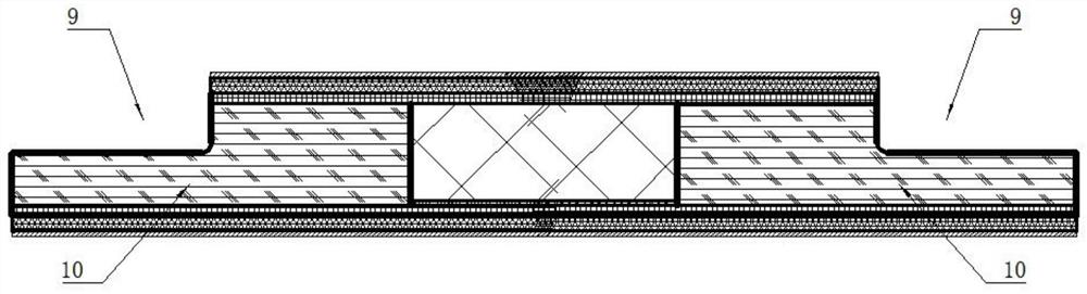
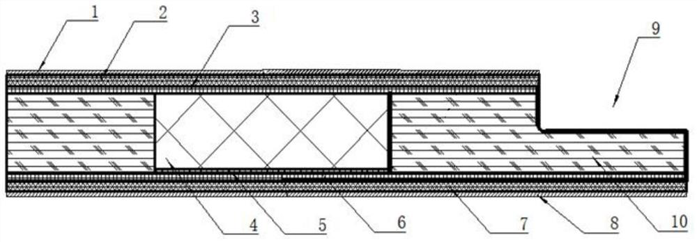
[0075] A fiber reinforced 3D composite floor, such as figure 1 with 2 As shown, from top to bottom include:

[0076] Upper fireproof layer 1, upper glass fiber composite cloth layer 2, upper glass fiber mesh cloth layer 3, 3D woven PU core material layer 4, sound insulation layer 5, lower glass fiber mesh cloth layer 6, lower glass fiber composite cloth layer 7 and the fireproof layer 8 on the bottom surface; the composite floor is infiltrated and reinforced with resin glue as a whole;

[0077] The four sides of the 3D woven composite floor are also provided with Z-shaped installation interfaces 9 that are connected to each other.

[0078] The 3D braided PU core material layer 4 is surrounded by an edge-sealing fireproof board 10 .

[0079] The manufacturing process of the above-mentioned fiber-reinforced 3D composite floor specifically includes the following steps:

[0080] Step 1. Preparation of the main material resin: 97 parts of epoxy vinyl resin, 1.5 parts of acceler...


PUM


Abstract

The invention provides a 3D woven composite floor and a manufacturing process thereof, and belongs to the technical field of floors. The composite floor sequentially comprises, from top to bottom: an upper fireproof layer, an upper glass fiber composite cloth layer, an upper glass fiber gridding cloth layer, a 3D woven PU core material layer, a sound insulation layer, a lower glass fiber gridding cloth layer, a lower glass fiber composite cloth layer and a bottom fireproof layer, wherein the whole composite floor is infiltrated and reinforced by resin adhesive; and fireproof plates are arranged on the periphery of the 3D woven PU core material layer. The invention further provides a manufacturing process of the 3D woven composite floor. The composite floor has the advantages of sound insulation, fire prevention, light weight, stripping resistance, aging resistance, medium resistance, moisture resistance, high strength and difficulty in deformation.

Description

technical field [0001] The invention belongs to the field of floor technology, and in particular relates to a 3D woven composite floor and a manufacturing process thereof. Background technique [0002] Railcar body interior floors are typically made of wood, aluminum honeycomb, or other materials. There are many classifications of floors, classified by material structure: plywood floor, aluminum honeycomb floor, phenolic resin composite floor, Basa wood composite floor, PET composite floor, PMI composite floor, etc.; classified by use: urban rail floor, subway floor, High-speed rail floor, intercity train floor, etc.; classified by function: soundproof floor, fireproof floor, lightweight floor, environmental protection floor, etc. [0003] With the rapid development of rail cars in China, more and more people have recognized rail cars as heavy vehicles in cities. At the same time, people have more and more requirements for environmental protection, sound noise, fire safety,...

Claims


Application Information

Patent Timeline
IPC IPC(8): B32B17/04B32B17/12B32B17/10B32B27/40B32B27/04B32B27/38B32B3/22B32B27/36B32B27/18B32B27/26B32B27/12B32B21/14B32B21/10B32B21/08B32B33/00B61D17/10C08L63/10C08J5/18C09D5/18C09D167/06B29C70/36B29C70/54
CPCB32B5/028B32B5/18B32B3/18B32B27/36B32B27/18B32B27/26B32B27/12B32B5/02B32B5/26B32B21/14B32B21/10B32B21/08B32B21/047B32B33/00B61D17/10C08J5/18C09D5/185C09D167/06B29C70/36B29C70/545B32B2262/101B32B2260/046B32B2266/0278B32B2307/102B32B2307/3065B32B2307/51B32B2307/554B32B2307/304B32B2307/714B32B2307/558B32B2307/734C08J2363/10
Inventor 张春来沈连涛李恒
Owner CHANGCHUN INTER CITY RAILWAY VEHICLE ACCESSORIES
Why Eureka
Try Eureka