
Fuel cell air-cooling integrated membrane electrode structure and preparation method thereof

A membrane electrode structure, fuel cell technology, applied in the direction of fuel cells, fuel cell additives, fuel cell heat exchange, etc. Simple, effective results

Active Publication Date: 2021-12-31
ZHEJIANG TIANNENG HYDROGEN ENERGY TECH CO LTD
View PDF9 Cites 0 Cited by
  • Summary
  • Abstract
  • Description
  • Claims
  • Application Information

AI Technical Summary

Problems solved by technology

[0004] Existing fuel cell metal bipolar plates are formed by integral die-casting of thin metal materials, and the hundreds of tons of presses and metal molds used to prepare and process bipolar plate products are expensive and often cost tens of millions.
[0005] The existing fuel cell bipolar plate has a structure of flow channel ridges and flow channel grooves, in which the flow channel ridges occupy a large volume and the volume utilization rate of the flow channel grooves is low. The effect is poor, and the flow channel itself has no moisturizing function
[0006] The existing air-cooled membrane electrodes do not integrate sealant lines and bipolar plates (flow channels). When assembling the stack, it is necessary to assemble a layer of sealant lines, a layer of bipolar plates, a layer of membrane electrodes, and a layer of sealant lines. , a layer of bipolar plate, and a layer of membrane electrode are so repeated, the process is complicated, the assembly workload is heavy, and the consistency is difficult to guarantee

Method used


Image

  • Fuel cell air-cooling integrated membrane electrode structure and preparation method thereof
  • Fuel cell air-cooling integrated membrane electrode structure and preparation method thereof
  • Fuel cell air-cooling integrated membrane electrode structure and preparation method thereof

Examples


Embodiment Construction

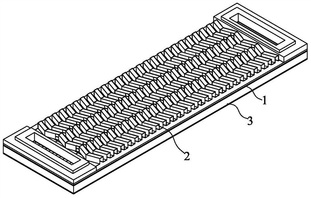
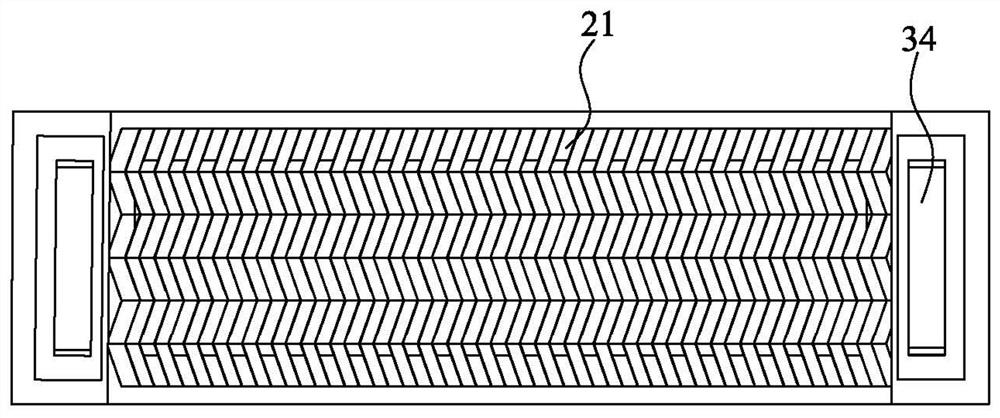
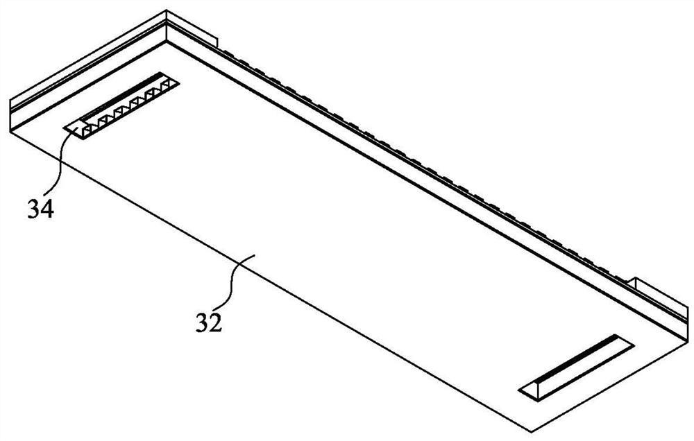
[0038] Such as Figure 1~12 As shown, an air-cooled integrated membrane electrode structure for a fuel cell includes a membrane electrode assembly 1 and an air flow channel layer 2 and a hydrogen flow channel layer 3 respectively located on both sides of the membrane electrode assembly. The air flow channel layer 2 is provided with air flow channels The hydrogen flow channel layer 3 is provided with hydrogen flow channels, wherein the hydrogen flow channels are arranged along the long axis of the membrane electrode assembly 1 , and the air flow channels are arranged along the short axis of the membrane electrode assembly 1 .

[0039] Such as Figure 5 , Figure 8~12As shown, the hydrogen flow channel layer 3 includes a hydrogen flow channel forming plate 31, the hydrogen flow channel forming plate 31 protrudes at intervals toward the membrane electrode assembly 1 to form hydrogen flow channel ridges 311, and a hydrogen flow channel ridge 311 is formed between two adjacent hyd...


PUM

PropertyMeasurementUnit
Thicknessaaaaaaaaaa

Abstract

The invention discloses an air-cooling integrated membrane electrode structure of a fuel cell and a preparation method of the air-cooling integrated membrane electrode structure. The air-cooling integrated membrane electrode structure of the fuel cell comprises a membrane electrode assembly, and an air flow channel layer and a hydrogen flow channel layer which are respectively positioned on two sides of the membrane electrode assembly, and the flow channel structure fully utilizes a flow channel ridge structure to form an extra flow channel in a hollow manner; and the bent part of the original runner groove is communicated through the opening (the first opening / the second opening) to form a shared runner, so that gas consumed by the membrane electrode can be more quickly supplemented under the same condition of gas runner space, the overall gas pressure distribution of the membrane electrode is uniform, the power density and the durability are improved, and the effect is more obvious especially under high current density. The structural assembly mode is simple, the hydrogen and air side flow channels and the sealing glue lines are integrated on the membrane electrode, one piece of integrated membrane electrode is a unit, dozens of or hundreds of units are assembled into a stack, the assembly steps are simplified, the stack assembly efficiency and consistency are improved, and the manufacturing cost is reduced.

Description

technical field [0001] The invention relates to the technical field of fuel cells, in particular to an air-cooled integrated membrane-electrode structure of a fuel cell and a preparation method thereof. Background technique [0002] The proton exchange membrane fuel cell is a device that converts the chemical energy in the fuel into electrical energy through a oxidation-reduction reaction with oxygen in the air, using hydrogen as the fuel. The general proton exchange membrane fuel cell structure consists of repeated stacking of bipolar plates (anode plate and cathode plate), membrane electrodes and some sealing components to form a stack containing a large number of single cell units. [0003] Among them, the air-cooled proton exchange membrane fuel cell uses air as the cooling medium, and the air is used not only for providing oxygen for reaction, but also for cooling. [0004] Existing fuel cell metal bipolar plates are integrally formed by die-casting thin metal material...

Claims


Application Information

Patent Timeline
IPC IPC(8): H01M8/0258H01M8/026H01M8/0263H01M8/021H01M8/0228H01M8/0267H01M8/0276H01M8/04014H01M8/1006
CPCH01M8/0258H01M8/0263H01M8/026H01M8/0276H01M8/021H01M8/0228H01M8/0267H01M8/04014H01M8/1006Y02E60/50Y02P70/50
Inventor 沈新龙曹寅亮方蕾茹皓孙基文李伯球徐乃涛徐淳川
Owner ZHEJIANG TIANNENG HYDROGEN ENERGY TECH CO LTD
Learn More