
Ceramic packaged power supply filter

A technology of power filter and ceramic packaging, which is applied in the direction of printed capacitors, electrical components, circuit devices, etc., can solve the problems of low weight, large dielectric constant, and gaps, and achieve high electrical efficiency, good heat dissipation and The effect of shielding and simple structure

Pending Publication Date: 2022-01-04
BEIJING YUANLIU HONGYUAN ELECTRONICS TECH +2
View PDF0 Cites 0 Cited by
  • Summary
  • Abstract
  • Description
  • Claims
  • Application Information

AI Technical Summary

Problems solved by technology

[0003] Metal shells are widely used in power filters due to their shielding effect. However, the combination of metal shells and circuit boards needs to be completed by welding, bonding, etc., which not only increases the complexity of the process, but also has gaps. It cannot achieve a completely sealed and shielded state; the plastic shell can meet the requirements of small size and low weight, but this type of material has a large dielectric constant, and when it is applied to a power filter, it will produce a large Parasitic parameters, especially parasitic capacitance, which couple high-frequency noise and affect the performance of the filter. On the other hand, the plastic shell has poor heat resistance and is not suitable for applications such as high current and high power.
[0004] At present, ordinary power filters mostly adopt the pin structure, that is, through welding or insulators, the pins are drawn out from the base as the lead-out end of the filter. This type of lead-out filter is only suitable for manual welding, and the efficiency is low.

Method used


Image

  • Ceramic packaged power supply filter
  • Ceramic packaged power supply filter
  • Ceramic packaged power supply filter

Examples


Embodiment Construction

[0025] In order to make the purpose, technical solutions and advantages of the embodiments of the present invention clearer, the technical solutions in the embodiments of the present invention will be clearly and completely described below in conjunction with the drawings in the embodiments of the present invention. Obviously, the described embodiments It is a part of embodiments of the present invention, but not all embodiments. Based on the embodiments of the present invention, all other embodiments obtained by persons of ordinary skill in the art without making creative efforts belong to the protection scope of the present invention.

[0026] In the description of the present invention, it should be noted that the terms "center", "upper", "lower", "left", "right", "vertical", "horizontal", "inner", "outer" etc. The indicated orientation or positional relationship is based on the orientation or positional relationship shown in the drawings, and is only for the convenience of...


PUM

PropertyMeasurementUnit
thicknessaaaaaaaaaa

Abstract

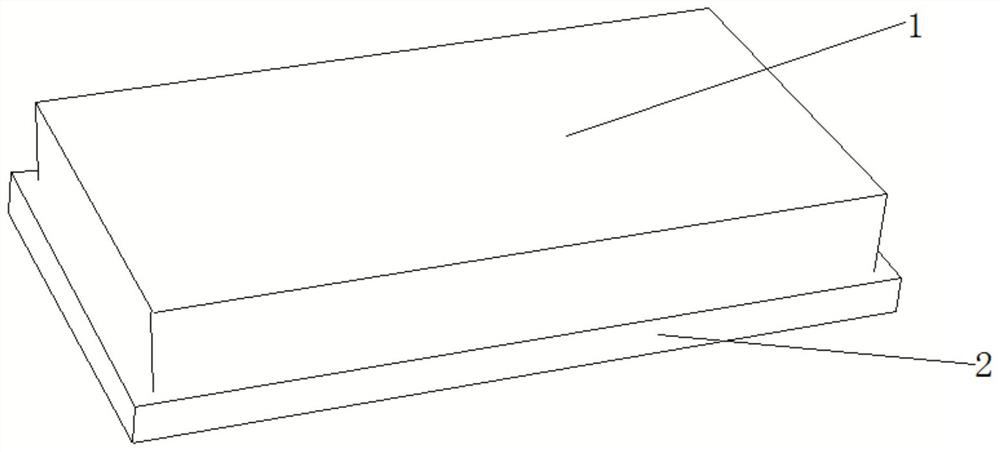
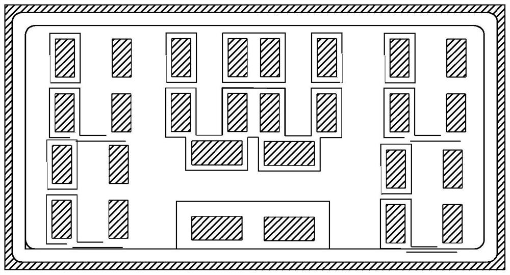
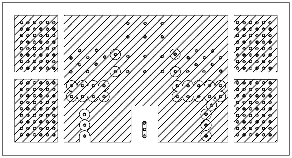
The invention discloses a ceramic packaged power supply filter, which comprises a base and a metal sealing frame, wherein the metal sealing frame and the base are co-fired into a whole at high temperature; the base is a high-thermal-conductivity ceramic base, and the high-thermal-conductivity ceramic base is of a multi-layer circuit board structure formed by alternately arranging ceramic layers and metal layers up and down; and the top layer of the high-thermal-conductivity ceramic base is used for installing a filtering component, the middle layer is used for a power supply layer or a shielding layer, the bottom layer is provided with bottom layer bonding pads used for leading-out ends of the filter, and each bottom layer bonding pad is electrically connected with the middle layer and the top layer through metalized via holes. The structure is simple, high-density interconnection is achieved through high-temperature co-firing of the high-thermal-conductivity ceramic base and the metal sealing frame and integration of a ceramic material and a metal material, good heat dissipation and shielding performance is achieved, the bottom layer bonding pad is arranged on the bottom layer of the base, the ceramic packaged power supply filter is suitable for the reflow soldering technology, and the electric fitting efficiency is far higher than that of manual welding.

Description

technical field [0001] The invention relates to the technical field of power filters, in particular to a ceramic-packaged power filter. Background technique [0002] At present, most of the power filters in the industry are metal shells, and the circuit boards use resin substrates or ceramic substrates. There are also a small part based on the requirements of small size and low weight, which use plastic shells, and circuit boards also use resin substrates. [0003] Due to its certain shielding effect, metal shells are widely used in power filters. However, the combination of metal shells and circuit boards needs to be completed by welding, bonding, etc., which not only increases the complexity of the process, but also has gaps. It cannot achieve a completely sealed and shielded state; the plastic shell can meet the requirements of small size and low weight, but this type of material has a large dielectric constant, and when it is applied to a power filter, it will produce a ...

Claims


Application Information

Patent Timeline
Patent Type & Authority Applications(China)
IPC IPC(8): H02M1/44H05K1/16H05K1/02
CPCH02M1/44H05K1/162H05K1/165H05K1/167H05K1/0203H05K1/0218
Inventor 赵玲革张士彦冀朝漪李跃田紫阳
Owner BEIJING YUANLIU HONGYUAN ELECTRONICS TECH
Learn More