Air valve one-time forming grinding machine

A valve and grinding machine technology, which is applied in the direction of grinding machines, grinding bed, grinding machine parts, etc., can solve the problems of reduced work efficiency, long operation time, and low work efficiency, and achieve simplified structure, reduced time consumption, and easy work The effect of improving efficiency

Active Publication Date: 2022-01-07
江苏吉斯特科技有限公司
View PDF7 Cites 1 Cited by
  • Summary
  • Abstract
  • Description
  • Claims
  • Application Information

AI Technical Summary

Problems solved by technology

Conventional valve grinding equipment, the valves are transported to the working area of ​​the grinding machine by the feeding device, and are clamped one by one to the front of the workpiece spindle of the grinding machine. The workpiece spindle is fixedly connected to the grinding machine bed, and the valves must be sent into the grinding machine through the clamping mechanism The chuck in the workpiece spindle is clamped and fixed, and after the grinding is completed, the valve is pushed out of the workpiece spindle through a ejector rod discharge mechanism. Such a valve clamping process requires corresponding feeding, clamping and other mechanisms. After the grinding is completed, a set of ejector rod discharge mechanism is required, which makes the grinding machine mechanism complex and takes a long time to operate. The grinding process is time-consuming due to the slow clamping process of the workpiece, and the work efficiency is not high; Grinding is an effective means to improve the grinding quality and grinding efficiency in the grinding process of the valve head. It can complete the grinding process of the valve head at one time. The forming grinding wheel needs to be ground frequently during use to maintain The grinding quality and efficiency are stable. The grinding wheel dresser in the commonly used forming grinding wheel dressing method is installed on the frame. When the forming grinding wheel needs to be dressed, the grinding wheel spindle is shifted to the dressing position corresponding to the grinding wheel dresser. The above-mentioned grinding wheel dressing method needs to arrange and set the grinding wheel dressing time and shift the grinding wheel spindle to the dressing position, so the normal production cycle of valve grinding needs to be interrupted, resulting in a decline in work efficiency

Method used


Image

  • Air valve one-time forming grinding machine
  • Air valve one-time forming grinding machine
  • Air valve one-time forming grinding machine

Examples


Embodiment Construction

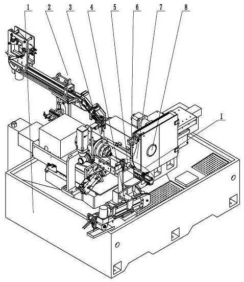
[0033] exist figure 1 In the one-time valve forming grinding machine shown, the frame 1 is the basic support of the valve grinding equipment, and the feeding conveying device 2, the hollow workpiece spindle 3, the grinding wheel spindle 8 and the discharging conveying device are supported on the frame 1 4. The valve 5 to be ground is conveyed to the front end of the workpiece spindle 3 by the feeding conveying device 2, and is positioned, clamped and rotated by the workpiece spindle 3 with the assistance of the loading positioning push rod 6, and is installed on the grinding wheel spindle 8 for forming The emery wheel carries out profile grinding on the head of the valve 5 to be ground, and the valve after grinding is output by the discharge conveying device 4 .

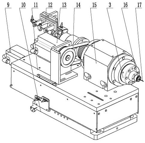
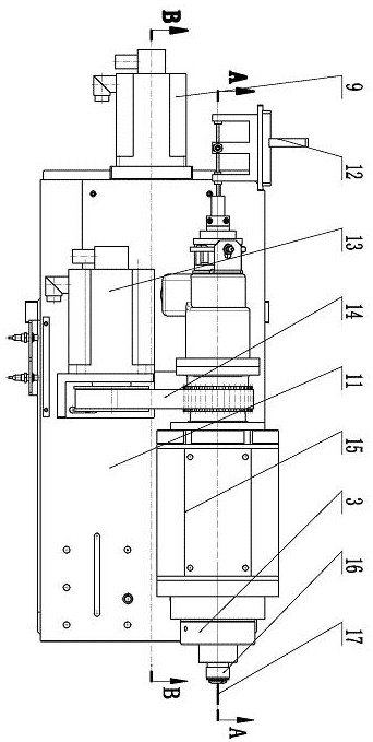
[0034] Such as figure 2 , image 3 with Figure 4 As shown, the workpiece spindle 3 is a hollow tubular member, and an elastic collet 16 is arranged at the front end of the inner hole of the workpiece spindle 3. ...


PUM


Abstract

The invention discloses an air valve one-time forming grinding machine which comprises a rack, a feeding conveying device, a discharging conveying device, a workpiece main shaft, a grinding wheel main shaft and a finishing wheel main shaft. The workpiece main shaft can move front and back in the axial direction through a workpiece main shaft sliding table. A discharging ejector rod limited through an ejector rod support and an elastic telescopic pin on the ejector rod support is inserted into an inner hole of an elastic chuck in the workpiece main shaft, an ejector rod position detection sensor is arranged on the ejector rod support, a charging positioning push rod capable of moving front and back is arranged at the front end of the workpiece main shaft, the grinding wheel main shaft, the finishing wheel main shaft and the workpiece main shaft are arranged in parallel, the grinding wheel main shaft moves and feeds in the radial direction through a grinding wheel sliding seat, and the finishing wheel main shaft is arranged on the grinding wheel sliding seat and can feed in the radial direction. By the adoption of the air valve one-time forming grinding machine, the structure of a clamping mechanism in valve grinding can be optimized, clamping and discharging are rapid and reliable, grinding wheel forming and finishing can be completed in time on the premise that the normal production takt of valve grinding is not affected, and the grinding quality and the production efficiency are improved.

Description

technical field [0001] The invention relates to a grinding device, in particular to a device for one-time forming grinding of a valve head. Background technique [0002] The manufacturing quality of the valve head is one of the key factors to ensure the performance of the engine, and the work efficiency in the valve manufacturing process is also the goal that the valve manufacturing industry is constantly pursuing. Conventional valve grinding equipment, the valves are transported to the working area of ​​the grinding machine by the feeding device, and are clamped one by one to the front of the workpiece spindle of the grinding machine. The workpiece spindle is fixedly connected to the grinding machine bed, and the valves must be sent into the grinding machine through the clamping mechanism The chuck in the workpiece spindle is clamped and fixed, and after the grinding is completed, the valve is pushed out of the workpiece spindle through a ejector rod discharge mechanism. Su...

Claims


Application Information

Patent Timeline
Patent Type & Authority Applications(China)
IPC IPC(8): B24B19/00B24B41/04B24B41/06B24B41/02B24B53/06B24B41/00B24B49/00
CPCB24B19/00B24B41/04B24B41/06B24B41/02B24B53/06B24B41/005B24B49/00Y02P70/10
Inventor 周红伟钟明华
Owner 江苏吉斯特科技有限公司
Why Eureka
Try Eureka