
Plasma heating furnace for melting shrinkage of optical fiber preform

A technology of optical fiber preform and plasma, applied in manufacturing tools, glass manufacturing equipment, etc., can solve the problems of low actual power, large heat loss, inconvenient maintenance, etc., and achieve improved reliability and life, small heating interval, and energy concentrated effect

Active Publication Date: 2022-01-07
FENGHUO COMM SCI & TECH CO LTD +1
View PDF2 Cites 0 Cited by
  • Summary
  • Abstract
  • Description
  • Claims
  • Application Information

AI Technical Summary

Problems solved by technology

[0003] The heat loss of the hydrogen-oxygen flame heating method is large, the actual power is relatively small, and the efficiency is low. Moreover, the moisture generated after combustion will increase the ambient humidity and affect the quality of the preform.
[0004] The heating method of graphite resistance furnace is complex and inconvenient to maintain. A large number of graphite parts are easy to oxidize and generate dust. The dust adheres to the preform, resulting in poor quality or scrap of the preform.

Method used


Image

  • Plasma heating furnace for melting shrinkage of optical fiber preform
  • Plasma heating furnace for melting shrinkage of optical fiber preform
  • Plasma heating furnace for melting shrinkage of optical fiber preform

Examples


Embodiment Construction

[0033] In order to make the purposes, technical solutions and advantages of the embodiments of the present application clearer, the technical solutions in the embodiments of the present application will be clearly and completely described below in conjunction with the drawings in the embodiments of the present application. Obviously, the described embodiments It is a part of the embodiments of this application, but not all of them. Based on the embodiments in the present application, all other embodiments obtained by persons of ordinary skill in the art without making creative efforts belong to the protection scope of the present application.

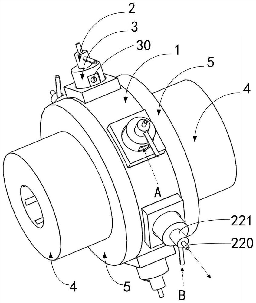
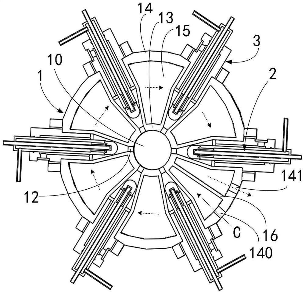
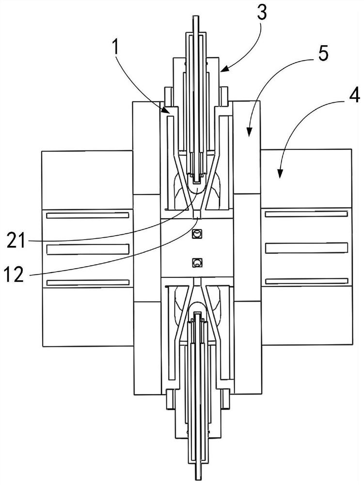
[0034] see figure 1 , figure 2 , graph and Figure 4 As shown, the embodiment of the present application provides a plasma heating furnace for melting and shrinking an optical fiber preform, which includes a furnace body 1 , several cathodes 2 and several insulating rings 3 . The furnace body 1 constitutes the anode, that is to say,...


PUM


Abstract

The invention relates to a plasma heating furnace for melting shrinkage of an optical fiber preform. The plasma heating furnace comprises a furnace body and a plurality of cathodes, the furnace body forms an anode, the furnace body is provided with a fusion shrinkage channel through which the optical fiber preform passes, a plurality of mounting cavities are formed in the furnace body, and the mounting cavities are communicated with the fusion shrinkage channel through plasma jet orifices; and the cathodes are arranged on the mounting cavities, working gas channels are formed between the cathodes and the mounting cavities, cathode heads of the cathodes face the plasma jet orifices, and insulating rings are arranged between the cathodes and the inner walls of the corresponding mounting cavities. The plasma heating furnace is provided with a melting shrinkage channel for the optical fiber preform to pass through, and working gas is introduced into the working gas channels to generate plasmas. A graphite piece is omitted in the furnace body, so that the situation that dust is generated through oxidation does not exist, no dust is attached to the optical fiber preform, and the quality of the optical fiber preform cannot be affected. The heating interval of the plasma flame generated by the plasma heating furnace is small, and compared with the related technical scheme, the energy is more concentrated and more energy-saving, and the efficiency is higher.

Description

technical field [0001] The present application relates to the technical field of optical fiber preform manufacturing, in particular to a plasma heating furnace for melting and shrinking optical fiber preforms. Background technique [0002] When the optical fiber preform is manufactured by the vapor deposition method, it is divided into two steps. The first step is deposition and the second step is shrinkage. The shrinkage is mainly to shrink the preform into a solid mandrel. Currently, the shrinkage heating methods commonly used include hydrogen-oxygen flame heating, graphite resistance furnace heating, and induction furnace heating. [0003] The hydrogen-oxygen flame heating method has large heat loss, low actual power and low efficiency, and the moisture generated after combustion will increase the ambient humidity and affect the quality of the preform. [0004] The heating method of the graphite resistance furnace is complex and inconvenient to maintain. A large number ...

Claims


Application Information

Patent Timeline
Patent Type & Authority Applications(China)
IPC IPC(8): C03B37/014C03B37/018C03B37/012
CPCC03B37/01446C03B37/01853C03B37/01257Y02P40/57
Inventor 闫雷曾建军胡博曲斌
Owner FENGHUO COMM SCI & TECH CO LTD
Learn More