Self-lubricating connecting rod plunger type valve flow distribution hydraulic pump

A technology of plunger type and hydraulic pumps, which is applied in variable capacity pump parts, parts of pumping devices for elastic fluids, pumps, etc., and can solve the problem of self-lubrication and friction of axial plunger pumps with water hydraulic valve distribution. Problems such as bad secondary force and large vibration and noise can achieve the effect of reducing the working load, prolonging the working life, and eliminating the alternating impact load and vibration and noise

Active Publication Date: 2022-01-07
BEIJING UNIV OF TECH
View PDF6 Cites 0 Cited by
  • Summary
  • Abstract
  • Description
  • Claims
  • Application Information

AI Technical Summary

Problems solved by technology

[0004] The purpose of the present invention is to provide a self-lubricating connecting rod plunger type valve distribution hydraulic pump, which overcomes the severe stress on the friction pair of the existing swash plate axial plunger pump, low working life, large leakage and vibration at high pressure. It has the disadvantages of high noise, large volume and weight, and the water hydraulic valve distribution axial plunger pump cannot self-lubricate. The grinding discs are ground against each other, and the wear-resistant discs are easy to replace and have bionic pits on the surface, which improves the maintainability and lubrication characteristics; when working, the low-pressure fluid fills the shell, and all friction pairs can achieve self-lubrication

Method used


Image

  • Self-lubricating connecting rod plunger type valve flow distribution hydraulic pump
  • Self-lubricating connecting rod plunger type valve flow distribution hydraulic pump
  • Self-lubricating connecting rod plunger type valve flow distribution hydraulic pump

Examples


Embodiment Construction

[0020] Below will combine the appended in the partial embodiment of the present invention Figure 1-Figure 4, the embodiments of the present invention will be described in more detail. Obviously, the described embodiments are only a part of all embodiments of the present invention. Other embodiments obtained directly or associatively from the disclosure of the present invention by persons of ordinary skill in the art without creative work, all belong to the protection scope of the present invention.

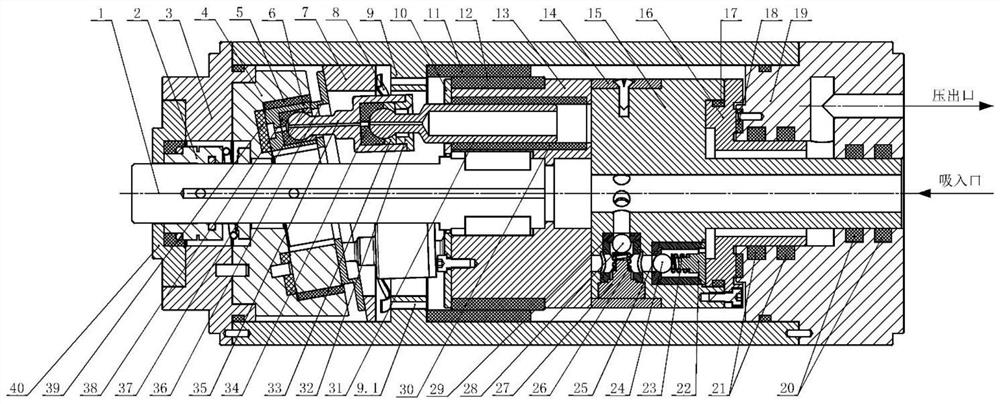
[0021] An embodiment of the present invention provides a self-lubricating connecting rod plunger valve distribution hydraulic pump. Such as figure 1 As shown, the front cover 3 is connected to the housing 9 by screws, and the housing 9 is connected to the rear end cover 19 by screws. The sealing gland 40 is installed on the front end cover 3 through screws and positioning notches, the mechanical seal 2 is installed inside the sealing gland 40, the swash plate 4 is fixed on the...


PUM


Abstract

The invention discloses a self-lubricating connecting rod plunger type valve flow distribution hydraulic pump which adopts a working mode of cylinder body rotary type valve flow distribution, rotating centrifugal force during working is beneficial to opening of a suction valve arranged in the radial direction, and the working pressure and suction performance of the pump are improved. A compact-structure non-spherical-hinge type return stroke mechanism and an integrated fixed connecting rod plunger are adopted, and sliding bearings are arranged on the outer circle of a connecting rod fixing disc and the outer circle of a cylinder body, so that lateral force of key components is effectively balanced. All friction pairs can achieve self-lubrication, a key friction pair is formed by pairing hard-hard materials of corrosion-resistant hard alloy and composite engineering ceramic, and a plane friction pair adopts a bionic texture to improve the lubrication and abrasion performance of the plane friction pair. The self-lubricating connecting rod plunger type valve flow distribution hydraulic pump has the obvious technical advantages of being high working pressure, large power-to-weight ratio, high pollution resistance, high reliability and the like, and can be widely applied to the ultrahigh pressure hydraulic system with hydraulic oil or pure water as a transmission medium.

Description

technical field [0001] The invention relates to a self-lubricating connecting rod plunger valve distribution hydraulic pump, which can be used as a power element in hydraulic transmission systems, and is especially suitable for hydraulic transmission systems with low-viscosity media (such as high water base and pure water hydraulic transmission systems, etc.) ), belonging to the technical field of fluid transmission and control. Background technique [0002] Hydraulic technology is a basic transmission and control technology that uses liquid as the working medium to generate, control and transmit liquid energy. It mainly uses the hydraulic pump to convert the mechanical energy of the prime mover into the pressure energy of the liquid, and realizes it through the change of the pressure energy of the liquid. Energy transmission, through various control valves and pipelines, with the help of actuators (cylinders or motors), the pressure energy of the liquid is converted into me...

Claims


Application Information

Patent Timeline
Patent Type & Authority Applications(China)
IPC IPC(8): F04B1/22F04B1/2078F04B1/2085F04B1/2035F04B1/2064F04B1/2014F04B1/122F04B53/08F04B53/18
CPCF04B1/22F04B1/2078F04B1/2085F04B1/2035F04B1/2064F04B1/2014F04B1/122F04B53/08F04B53/18
Inventor 尹方龙纪辉聂松林
Owner BEIJING UNIV OF TECH
Why Eureka
Try Eureka