Oil sludge treatment system

A treatment system and oil sludge technology, applied in sludge treatment, water/sludge/sewage treatment, sludge treatment through temperature control, etc., can solve the problem that sludge, oil and water are not completely separated, there are many particles in wastewater, equipment Problems such as large footprint, to achieve the effect of saving one-time investment, small footprint, and saving floor space

Pending Publication Date: 2022-01-11
北京美斯顿科技开发有限公司
View PDF4 Cites 0 Cited by
  • Summary
  • Abstract
  • Description
  • Claims
  • Application Information

AI Technical Summary

Problems solved by technology

However, the process of the existing oil sludge heat treatment technology is relatively complicated, the equipment occupies a large area, and the oil content in the sludge after treatment is relatively high, and there are many particles in the wastewater obtained. After the sludge treatment, the sludge, oil and water Not completely separated, low processing efficiency

Method used


Image

  • Oil sludge treatment system
  • Oil sludge treatment system
  • Oil sludge treatment system

Examples


Embodiment 1

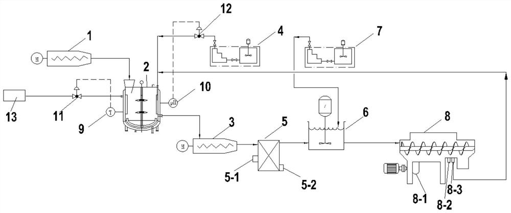
[0040] Such as figure 1 , an oil sludge treatment system, including a feeding device 1, an integrated oil sludge crushing and conditioning device 2, an oil sludge pump 3, a first dosing skid 4, a heat exchange device 5, a mixing tank 6, a second dosing skid 7 and three phase centrifugal separation device 8; the feeding device 1, the oil sludge crushing and conditioning integrated device 2, the sludge pump 3, the heat exchange device 5, the mixing tank 6 and the three-phase centrifugal separation device 8 are sequentially connected; the oil sludge crushing and conditioning A heat source inlet 2 - 1 is provided on the integrated device 2 ; the first chemical dosing skid 4 is connected to the integrated device 2 for oil sludge crushing and tempering, and the second chemical dosing skid 7 is connected to the mixing tank 6 .

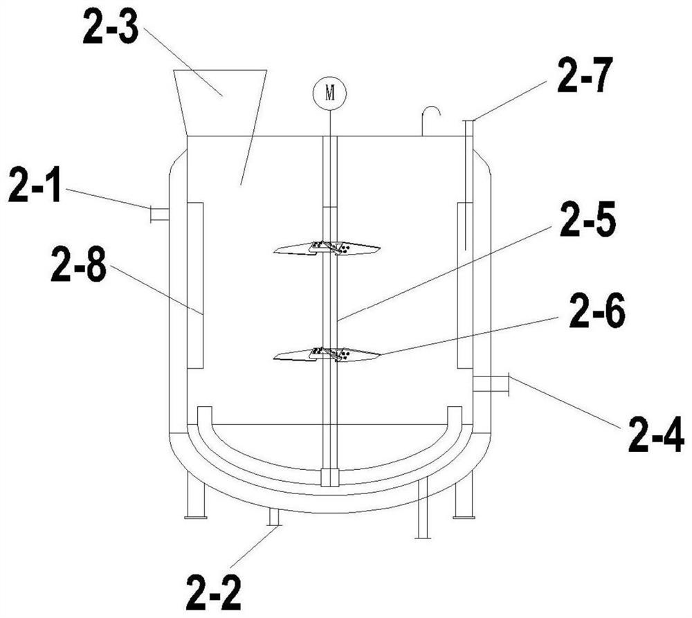
[0041] Such as figure 2 A temperature control device 9 is provided on the sludge crushing and conditioning integrated device 2, the heat source inlet 2-1 i...

Embodiment 2

[0044] Adopt the oil sludge treatment system of embodiment 1 to carry out oil sludge treatment, the source of the oil sludge adopted is tank bottom oil sludge, and the treatment process is:

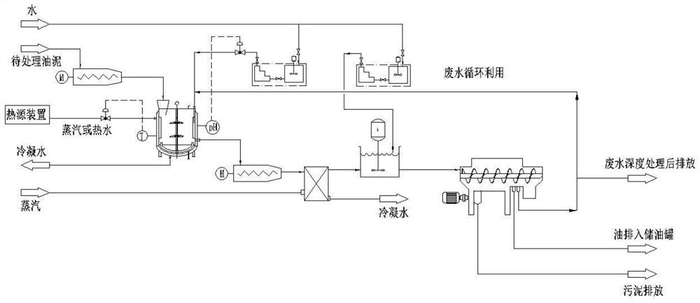
[0045] Such as figure 1 , figure 2 and image 3 The oil sludge enters the oil sludge crushing and tempering integrated device 2 through the feeding device 1, and heat sources such as steam or hot water are passed from the heat source device 5 through the heat source inlet 2-1 into the oil sludge crushing and conditioning integrated device 2 to heat the oil sludge , and the heating temperature is controlled by the temperature control device 9 to be 90°C, and the dilution water is added to the sludge crushing and tempering integrated device 2 through the water inlet pipe 2-7 to dilute the sludge, and the sludge is crushed in the sludge crushing and conditioning integrated device 2 , demulsification, dilution and stirring. During the stirring process, the demulsifier potassium persulfate ...


PUM


Abstract

The invention provides an oil sludge treatment system. The oil sludge treatment system comprises a feeding device, an oil sludge crushing and tempering integrated device, an oil sludge pump, a first dosing pry, a heat exchange device, a mixing tank, a second dosing pry and a three-phase centrifugal separation device, the feeding device, the oil sludge crushing and tempering integrated device, the oil sludge pump, the heat exchange device, the mixing tank and the three-phase centrifugal separation device are connected in sequence; a heat source inlet is formed in the oil sludge crushing and tempering integrated device; and the first dosing pry is connected to the oil sludge crushing and tempering integrated device, and the second dosing pry is connected to the mixing tank. Compared with an oil sludge treatment system in the prior art, the oil sludge treatment system greatly simplifies the oil sludge treatment process, remarkably simplifies treatment equipment, and is high in oil sludge treatment efficiency; the system is an efficient and energy-saving oil sludge treatment system, the occupied area and one-time investment can be effectively saved; and the system is low in treatment cost, low in energy consumption, economical, efficient and easy to put into production.

Description

technical field [0001] The invention relates to the field of oil sludge treatment, in particular to an oil sludge treatment system. Background technique [0002] Sludge is a pollutant produced in various stages of crude oil processing. It is not only complex in composition, but also highly polluting. Once discharged into the ecological environment, it will cause serious pollution to the water, soil and air in the environment. With the increasingly stringent environmental protection requirements, oily sludge reduction, harmless, and resourceful treatment have become an inevitable trend in the development of oily sludge treatment technology. [0003] Heat treatment technology is a relatively stable technology among oily sludge treatment technologies, with strong program operability, low energy consumption, low investment, cost-effective and easy to put into production. However, the process of the existing oil sludge heat treatment technology is relatively complicated, the equ...

Claims


Application Information

Patent Timeline
Patent Type & Authority Applications(China)
IPC IPC(8): C02F11/00C02F11/18C02F11/13C02F11/14C02F11/127
CPCC02F11/00C02F11/18C02F11/13C02F11/14C02F11/127
Inventor 李慧海娇张良平田凯盖英会杨学琴武鹏永闫东生李宁
Owner 北京美斯顿科技开发有限公司
Why Eureka
Try Eureka