Secondary composite casting bimetal forming method

A composite casting, bimetal technology, applied in the field of bimetal casting, can solve the problems of poor strength stability, reduced bearing capacity, reduced engine life, etc., to achieve the effect of good interface bonding performance, increased service life, and reduced time

Pending Publication Date: 2022-01-14
ZHONGBEI UNIV
View PDF8 Cites 0 Cited by
  • Summary
  • Abstract
  • Description
  • Claims
  • Application Information

AI Technical Summary

Problems solved by technology

The engine block usually adopts a solid-liquid composite casting method, but the dissimilar metals cannot achieve complete metallurgical bonding during the casting process, especially some cracks will be formed at the joint, these cracks will make the load unable to Efficient, smooth and uniform transmission, the engine will force cracks to continue to grow under normal working conditions, and the engine will continue to undergo fatigue cycles during operation, resulting in reduced engine life or permanent damage
Therefore, the poor stability of the bonding strength will lead to the problem of reduced bearing capacity often occurs

Method used


Image

  • Secondary composite casting bimetal forming method
  • Secondary composite casting bimetal forming method
  • Secondary composite casting bimetal forming method

Examples


Embodiment 1

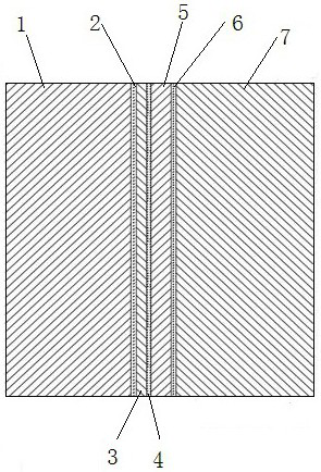
[0027] 1. The surface of the steel substrate is cleaned, and a layer of bonding material 3 is plated on the surface of the steel substrate 1 by electroless plating. The bonding material 3 is copper with a thickness of 1 mm. A first bonding interface 2 is formed between the bonding material 3 and the steel matrix 1 .

[0028] 2. Clean and purge the mold with argon, then place the copper-plated steel substrate in the mold, and turn on the intermediate frequency induction heating coil to preheat the steel substrate; the preheating temperature is 600°C, and the power is 45KW.

[0029] 3. Put the aluminum alloy ingot into the crucible furnace for melting, and the melting temperature is 780°C.

[0030] 4. Turn off the intermediate frequency induction heating coil, and pour the smelted aluminum alloy melt into the mold to form the first casting melt 5 on the surface of the copper-coated steel substrate.

[0031] 5. After the pouring is finished, after the mold is cooled, the workpie...

Embodiment 2

[0037] 1. The surface of the steel substrate is cleaned, and a layer of nickel is plated on the surface of the steel substrate by electroless plating, with a thickness of 0.7mm.

[0038] 2. Clean and purge the mold with argon, then place the copper-plated steel substrate in the mold, and turn on the intermediate frequency induction heating coil to preheat the steel substrate; the preheating temperature is 600°C, and the power is 45KW.

[0039] 3. Put the aluminum alloy ingot into the crucible furnace for melting, and the melting temperature is 780°C.

[0040] 4. Turn off the intermediate frequency induction heating coil, and pour the smelted aluminum alloy melt into the mold.

[0041] 5. After the pouring is finished, take out the workpiece after the casting mold is cooled for finishing. The thickness of the aluminum alloy is 7mm.

[0042] 6. Preheat the workpiece after processing; the preheating temperature is 600°C and the power is 45KW.

[0043] 7. Clean and purge the eng...


PUM

PropertyMeasurementUnit
thicknessaaaaaaaaaa
thicknessaaaaaaaaaa
thicknessaaaaaaaaaa

Abstract

The invention discloses a secondary composite casting bimetal forming method, and belongs to the technical field of bimetal casting. The method comprises the following steps: arranging a bonding material on the surface of a metal matrix, putting the matrix of the bonding material into a casting mold or a sand mold, pouring the molten aluminum alloy into the casting mold or the sand mold to bond the aluminum alloy with the matrix, then putting the metal matrix into a casting mold or a sand mold used for secondary casting, pouring the molten aluminum alloy to form a secondary composite casting part, and finally performing heat treatment on the secondary composite casting part. According to the method of the invention, through secondary pouring, a second bonding interface of the same metal is further formed outside a bonding interface of dissimilar metal; and aluminum-aluminum same metal bonding is formed through secondary casting, better atomic diffusion can be achieved to form metallurgical bonding compared with traditional dissimilar metal bonding, and the problem that the bonding performance of a dissimilar metal bonding interface is low is solved.

Description

technical field [0001] The invention belongs to the technical field of bimetal casting, and in particular relates to a bimetal forming method of secondary composite casting. Background technique [0002] Aluminum-steel bimetal materials are widely used in the automotive field, such as engine block, engine piston, brake disc, gearbox and other structures. The use of aluminum engines reduces the fuel consumption by 6% to 8% for every 10% reduction in vehicle weight. However, there are still some cast iron materials inside the aluminum cylinder engine, especially the cylinder, which should use cast iron materials. The engine block usually adopts a solid-liquid composite casting method, but the dissimilar metals cannot achieve complete metallurgical bonding during the casting process, especially some cracks will be formed at the joint, these cracks will make the load unable to Efficient, smooth and uniform transmission, the engine will force cracks to continue to grow under no...

Claims


Application Information

Patent Timeline
Patent Type & Authority Applications(China)
IPC IPC(8): B22D19/16
CPCB22D19/16B22D19/0081
Inventor 张国伟王赵杰徐宏任晓燕万安
Owner ZHONGBEI UNIV
Why Eureka
Try Eureka