
Molten salt reactor core and molten salt reactor system

A technology for molten salt reactors and cores, applied in reactors, reactor fuel materials, nuclear power generation, etc., can solve problems such as high construction costs, high thresholds, and low heat exchange efficiency, and improve operational safety, simplify structures, and improve The effect of heat transfer efficiency

Pending Publication Date: 2022-01-14
SHANGHAI INST OF APPLIED PHYSICS - CHINESE ACAD OF SCI
View PDF0 Cites 2 Cited by
  • Summary
  • Abstract
  • Description
  • Claims
  • Application Information

AI Technical Summary

Problems solved by technology

[0005] The technical problem to be solved by the present invention is to overcome the defects of complex heat pipe reactor core structure, low heat exchange efficiency, high construction cost, high threshold, poor safety, and low power generation power of molten salt reactor system in the prior art, and provide a Molten salt reactor core and molten salt reactor system

Method used


Image

  • Molten salt reactor core and molten salt reactor system
  • Molten salt reactor core and molten salt reactor system
  • Molten salt reactor core and molten salt reactor system

Examples


Embodiment 1

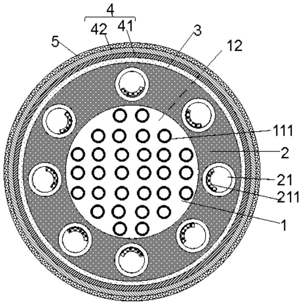
[0080] Such as figure 1 As shown, the coolant pipeline area 11 of the molten salt reactor core includes a coolant pipeline 111, a collection pipeline 112 and a distribution pipeline 113. The top end of the coolant pipeline 111 communicates with the collection pipeline 112, and the bottom end of the coolant pipeline 111 communicates with the distribution pipeline. 113 is connected; the collection pipe 112 is connected with the coolant outlet 6, and the distribution pipe 113 is connected with the coolant inlet 7; the coolant is circulated in the coolant pipe 111, and the coolant is a mixture of helium and xenon, and the molar ratio of xenon is 9.1% , the number of coolant pipes 111 is 121, the inner diameter of the coolant pipe 111 is 3.2cm, the material of the coolant pipe 111 is SiC, the wall thickness is 1mm, and the average flow velocity of the coolant in the coolant pipe 111 is 30m / s or so.

[0081] The molten salt reactor core includes core active area 1 , reflection lay...

Embodiment 2

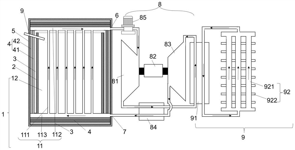
[0089] Such as image 3 As shown, the molten salt reactor system includes the molten salt reactor core of Embodiment 1, a thermoelectric conversion system 8 and a waste heat removal system 9 . The coolant outlet 6 of the molten salt reactor core is connected to the inlet of the thermoelectric conversion system 8 , and the coolant inlet 7 is connected to the outlet of the thermoelectric conversion system 8 .

[0090]The thermoelectric conversion system 8 includes a turbine 81, a generator 82, a compressor 83, a regenerator 84, and a coolant pump 85. The inlet of the turbine 81 is connected to the coolant outlet 6, and the turbine 81 is connected to the generator 82. The coolant The coolant flowing out of the outlet 6 has a temperature of 700°C and a gas pressure of 2 MPa. It expands adiabatically through the turbine 81 to perform work to the outside, and drives the generator 82 to generate electricity; the outlet of the turbine 81 is connected to the inlet of the compressor 83,...


PUM


Abstract

The invention discloses a molten salt reactor core and a molten salt reactor system. The molten salt reactor core comprises a reactor core active area, a reflecting layer, a coolant inlet and a coolant outlet, the reflecting layer is arranged around the outer side of the reactor core active area, and a control drum is arranged in the reflecting layer; the reactor core active area is provided with a coolant pipeline area and a fuel molten salt area, the coolant pipeline area is provided with a plurality of coolant pipelines, and helium and xenon mixed gas or supercritical carbon dioxide circulates in the coolant pipelines; the fuel molten salt area is filled with fuel molten salt; the volume ratio of the coolant pipeline area to the fuel molten salt area is (6-9):10; and the top end of the coolant pipeline is connected with the coolant outlet, and the bottom end of the coolant pipeline is connected with the coolant inlet. The molten salt reactor core is simple in structure, the heat exchange efficiency of the reactor core is improved, the construction cost and the construction threshold of the reactor core are reduced, operation is safer, and meanwhile the electric power of a molten salt reactor system is improved to a great extent.

Description

technical field [0001] The invention relates to a molten salt reactor core and a molten salt reactor system. Background technique [0002] Nuclear power has the advantages of high energy density, stable working performance, and good environmental adaptability, which can provide a strong guarantee for deep space, deep sea exploration, and stable energy supply in remote areas. Different from conventional large commercial reactors, small reactors have advantages in terms of construction period, construction cost risk, operational safety and deployment flexibility. Small reactors have attracted widespread attention from countries all over the world, especially countries with developed nuclear energy, such as the United States and Russia. The United States has launched space reactor research projects since the 1960s, and has developed a variety of space reactors, including the SNAP series of space reactors, 710 space reactors, and SP-100 space reactors; after 2000, the Prometheu...

Claims


Application Information

Patent Timeline
Patent Type & Authority Applications(China)
IPC IPC(8): G21C15/14G21C3/54G21C15/10
CPCG21C3/54G21C15/14G21C15/10Y02E30/30
Inventor 伍建辉蔡翔舟陈金根邹春燕余呈刚邹杨赵宏凯
Owner SHANGHAI INST OF APPLIED PHYSICS - CHINESE ACAD OF SCI
Learn More