
Power grid direct-current flexible loop closing control device and control method thereof

A ring control and flexible technology, applied in the field of distribution network optimization operation control, can solve the problems of large equipment capacity and operation loss, unable to guarantee reliable power supply, and limit application and promotion, so as to improve power supply reliability, simple structure, and avoid downtime. The effect of load operation

Active Publication Date: 2022-01-21
NANJING HEXI ELECTRIC CO LTD +2
View PDF5 Cites 2 Cited by
  • Summary
  • Abstract
  • Description
  • Claims
  • Application Information

AI Technical Summary

Problems solved by technology

However, there are also the following problems: all of them basically use a single power supply to close the loop. Although the reliability of this method is improved compared with the open-loop operation, it cannot guarantee reliable power supply when the upper-level power grid fails.
However, the current flexible interconnection devices are composed of back-to-back / multi-port power electronic converters, which also have the problems of excessive equipment capacity, large operating loss, and high operation and maintenance costs.
It can be seen that the equipment utilization rate of this kind of flexible ring closing device is low, and the comprehensive cost is high, which will greatly limit its application and promotion.

Method used


Image

  • Power grid direct-current flexible loop closing control device and control method thereof
  • Power grid direct-current flexible loop closing control device and control method thereof
  • Power grid direct-current flexible loop closing control device and control method thereof

Examples


Embodiment Construction

[0052] The technical solution of the present invention will be further specifically described below in conjunction with the accompanying drawings.

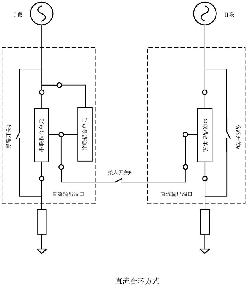
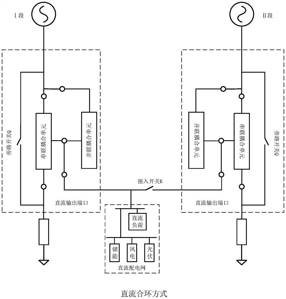
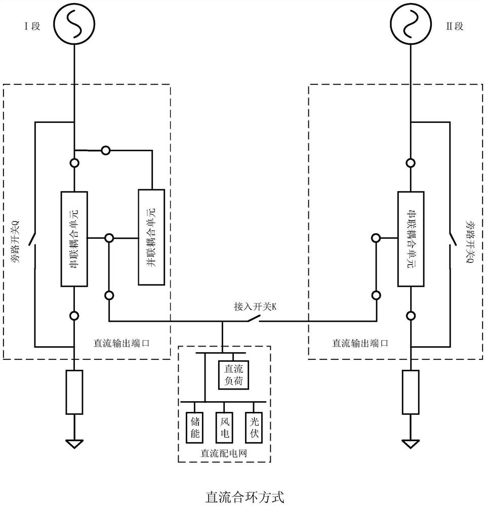
[0053] Step 1, establish the system model of the grid DC flexible loop closing device, such as figure 1 shown. The device in this embodiment includes two sets of series-parallel devices and one set of access switches. Each group of series-parallel devices is connected in series between each section of distribution line and the load, and connects the DC ports of the flexible ring-closing device in the ring-closing platform to realize DC-loop closing. Each series-parallel device includes two AC output ports and one DC output port. The interior is composed of a series coupling unit, a parallel coupling unit, a bypass switch and a DC loop closing main controller. The two AC ports of the three-port series coupling unit are connected in series to the line, and the DC ports are connected to the DC side of the parallel coupling unit. ...


PUM


Abstract

The invention discloses a power grid direct-current flexible loop closing control device and a control method thereof. The device is a series-parallel connection device and comprises a series connection coupling unit, a parallel connection coupling unit, other bypass switch circuits and a loop closing main controller, wherein each group of series-parallel connection device is connected in series between each section of power distribution line and load, after a loop closing instruction is received, a loop closing control device is set to work in a voltage control mode, when the direct-current bus voltages of the two groups of loop closing devices are consistent, the system enters a loop closing state, and before loop closing is quitted, the device is set to be in a PQ control mode, access switches are sequentially disconnected after P and Q are gradually reduced to zero, and the loop closing process is ended. According to the invention, the device has the advantages of being simple in structure, low in cost, less in loop closing monitoring amount compared with alternating current loop closing, and high in efficiency; and flexible power mutual aid and fault rapid exit can be realized, the power factor of the closed loop zone area is adjusted to be optimal, the power supply mode of the distribution network can be flexibly changed, and the new energy consumption level and the direct current load accepting capability are improved.

Description

technical field [0001] The invention belongs to the technical field of distribution network optimization operation control, and in particular relates to a flexible DC loop closing control device for power grids and a control method thereof. Background technique [0002] The existing power distribution system faces the problems of insufficient power supply capacity, difficulty in ensuring power quality, and low power supply reliability. In order to optimize the network structure, the traditional distribution network uses sectional switches and tie switches for closed-loop, but it cannot achieve power flexibility and mutual aid, and because of the voltage difference and phase difference at the closing point, it is easy to cause a large inrush current, which affects the safe and stable operation of the power grid. . At present, there are related research and demonstration projects to improve the reliability of power supply, such as petal-shaped distribution network, honeycomb ...

Claims


Application Information

Patent Timeline
Patent Type & Authority Applications(China)
IPC IPC(8): H02J3/00H02J3/02H02J3/06H02J3/28H02J3/38H02J1/08H02J1/10H02J1/14H02J13/00
CPCH02J3/001H02J3/0073H02J3/02H02J3/06H02J3/28H02J3/381H02J1/086H02J1/10H02J1/14H02J13/00002H02J2203/20H02J2300/24H02J2300/28Y02E10/56Y02E40/70Y02E60/00Y04S10/12Y04S10/14Y02E60/60
Inventor 黄晓辉刘承锡顾维菱李伟李志国
Owner NANJING HEXI ELECTRIC CO LTD
Learn More