Use of renewable energy in olefin synthesis

A technology for olefins and light olefins, applied in the field of electrification, which can solve problems such as energy efficiency loss

Pending Publication Date: 2022-01-21
SABIC GLOBAL TECH BV
View PDF6 Cites 1 Cited by
  • Summary
  • Abstract
  • Description
  • Claims
  • Application Information

AI Technical Summary

Problems solved by technology

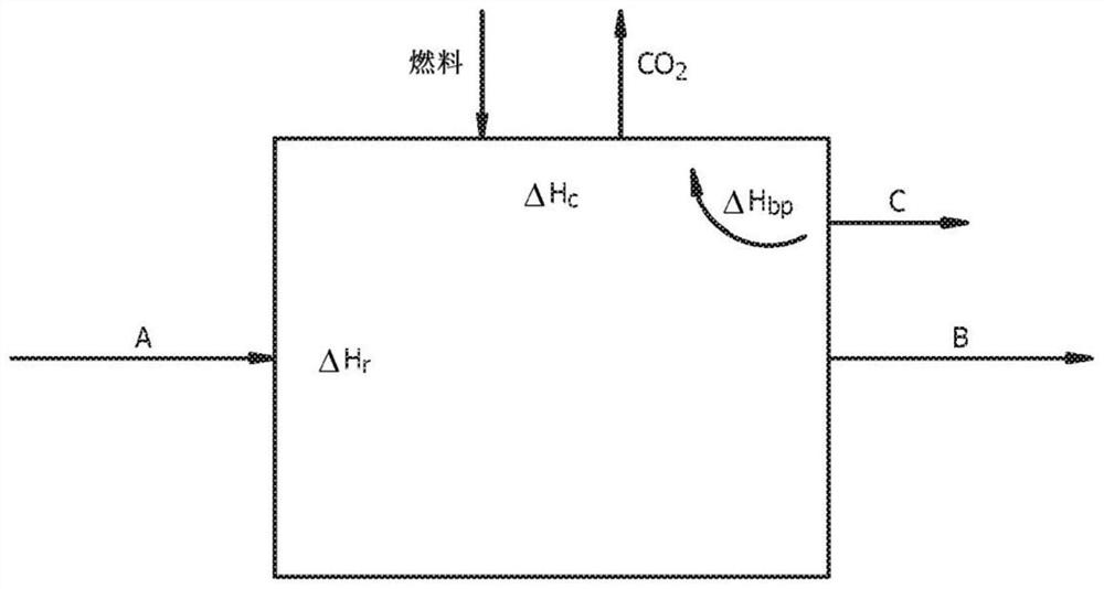
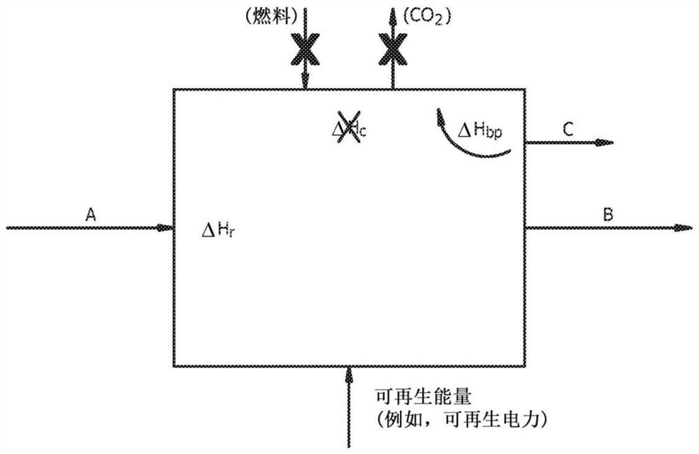
Steam for heat and / or energy transfer is often generated by the combustion of fuels, resulting in additional smoke generation and further loss of energy efficiency during chemical synthesis
In addition, the use of materials that would otherwise be available as reactants for combustion as fuel also reduces the amount of desired chemical product produced from a given amount of material in a chemical synthesis facility

Method used


Image

  • Use of renewable energy in olefin synthesis
  • Use of renewable energy in olefin synthesis
  • Use of renewable energy in olefin synthesis

Examples


Embodiment

[0119] Having generally described the embodiments, the following examples are given as specific embodiments of the disclosure and demonstrate the practice and advantages thereof. It should be understood that these examples are given by way of illustration and are not intended to limit the description or the claims in any way.

[0120] in relation to the example Figure 5-9 In , the lightning bolt symbol is used to denote electricity, especially renewable electricity, while the triple elongated "S" symbol is used to denote steam usage. exist Figure 5-9 and in the description of the embodiments below, pumps and miscellaneous energy banks are indicated at 217 .

Embodiment 1

[0129] Example 1 is the partial electrification of the steam cracking process described in Comparative Example 1 according to one embodiment of the present disclosure. In Example 1, the auxiliary boiler is removed and the energy supplied to the boiler by burning natural gas is replaced by a smaller amount of renewable electricity. This substitution of external energy required some reconfiguration of the energy integration of the process; in Example 1, the most important differences were that (1) the cryogenic refrigeration system and some pumps were now driven by electric motors, (2) the recirculated water was evaporated to Some of the energy required to make the diluent vapor is provided by electrical heating, and (3) the TLE is replaced by a heat exchanger system so that much of the heat recovered from cooling the hot product gas is used to preheat the feed gas.

[0130] Image 6The key elements of the electrification device IV of Embodiment 1 are shown in . As in Comparat...

Embodiment 2

[0135] Example 2 is a full electrification of the steam cracking process described in Comparative Example 1 according to one embodiment of the present disclosure. In Example 2, the energy supplied by the natural gas-fired auxiliary boiler and cracking furnace in Comparative Example 1 was replaced by renewable electricity that powered all compressors and pumps, powered cracking, and recirculated and make-up water The evaporation provides heat. Additionally, the TLE of Comparative Example 1 was replaced by a heat exchanger system such that much of the heat recovered from cooling the hot product gas was used to preheat the feed gas. These changes allow elimination of the process steam system and complete avoidance of flue gas losses.

[0136] Figure 7 Key elements of the electrification device V of Embodiment 2 are shown in . The ethane feed 205 in an amount of 236 t / hr is combined with the recycle gas in the ethane recycle stream 242 and the diluent steam in the dilution ste...


PUM


Abstract

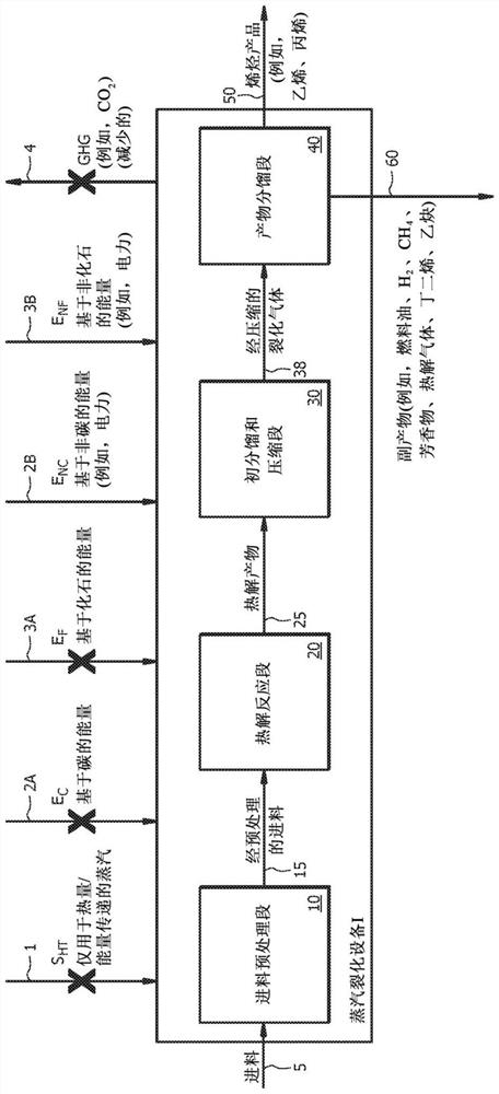
An olefin synthesis plant comprising: a feed pretreatment section configured to pretreat a feed stream; a pyrolysis section comprising one or more pyrolysis reactors configured to crack hydrocarbons in the feed stream in the presence of a diluent to produce a cracked gas stream; a primary fractionation and compression section configured to provide heat recovery from and quenching of the cracked gas stream; remove a component from the cracked gas stream; and compress the cracked gas stream, thus providing a compressed cracked gas stream; and / or a product separation section configured to separate a product olefin stream from the compressed cracked gas stream, wherein the olefin synthesis plant is configured such that, relative to a conventional olefin synthesis plant, more of the energy and / or the net energy required by the olefin synthesis plant and / or one or more sections thereof, is provided by a non-carbon based and / or renewable energy source and / or electricity.

Description

technical field [0001] The present disclosure relates to the use of renewable energy in the synthesis of olefins; more particularly, the present disclosure relates to the electrification of olefin synthesis plants; natural gas / fossil fuels) to reduce environmental emissions such as carbon dioxide. Background technique [0002] Chemical synthesis equipment is used to provide a variety of chemicals. Typically, specialized fuels are burned or "burned" to provide reaction heat for chemical synthesis, energy to heat one or more process streams, energy to vaporize liquids (e.g., using boiling water as a diluent), work (e.g., to drive a compressor or pump) ) or energy for other process operations of the entire chemical synthesis facility. Such flaring or burning of fuels leads to the generation of fumes which may be harmful to the environment, and also leads to a loss of energy efficiency of the process. Likewise, steam has traditionally been utilized as a plant-wide heat and / or...

Claims


Application Information

Patent Timeline
Patent Type & Authority Applications(China)
IPC IPC(8): C10G15/08C07C5/02C10G7/02
CPCY02P20/133C07C29/1518C07C31/04C07C1/02C07C7/148C07C11/04C07C11/06H02J15/008B01D53/265C01B3/48C01B2203/0233C01B2203/0244C01B2203/0261C01B2203/0283C01B2203/04C01B2203/061C01B2203/066C01B2203/085C01B2203/148C07C29/152F25J3/0233H01M8/0618H02J15/006C01B3/12C01B2203/0238C01B2203/0294C01B2203/068C01C1/0417C01C1/0488B01D53/047B01D2256/16B01D2256/245B01J19/2465B01J2219/00051C01B3/342C01B3/56C01B2203/0216C01C1/02C07C4/02C07C29/132H01M8/04201H01M8/0606H01M8/1007B01J6/008C07C4/04B01J4/008B01J19/0033B01J19/0053B01J2219/00132B01J2219/00761B01J2219/0871
Inventor 安德鲁·马克·沃德斯科特·史蒂文森阿诺·奥普林斯赵准蒂姆·阿尔伯特肯尼思·弗朗西斯·劳森约瑟夫·威廉·施罗尔迈克尔·爱德华·哈克曼
Owner SABIC GLOBAL TECH BV
Why Eureka
Try Eureka