Multi-signal optimization energy-saving electric precipitation control method

A control method and electrostatic precipitator technology, applied in design optimization/simulation, power supply technology, electrostatic separation, etc., can solve problems such as high power consumption of electric precipitator equipment, impact on power plant production efficiency, energy waste, etc., to reduce back corona and Secondary flying of dust, reasonable rapping cycle and interval, and reduced power consumption

Pending Publication Date: 2022-01-28
HUANENG QUFU THERMAL POWER CO LTD
View PDF0 Cites 2 Cited by
  • Summary
  • Abstract
  • Description
  • Claims
  • Application Information

AI Technical Summary

Problems solved by technology

[0003] With the increasingly stringent national environmental protection control policies, ultra-low emissions have become a new benchmark for coal-fired power generation units. In order to reduce dust emissions from power plants, factories must use a variety of dust removal equipment including electrostatic precipitators. In order to achieve ultra-low Emission standards, full-load operation of the electrostatic precipitator consumes a lot of power and energy consumption, which will have a certain degree of impact on the production efficiency of the power plant and cause unnecessary waste of energy. The equipment is transformed and optimized to minimize the high energy consumption of the electrostatic precipitator due to various unreasonable factors without reducing the dust removal efficiency and requirements

Method used


Image

  • Multi-signal optimization energy-saving electric precipitation control method
  • Multi-signal optimization energy-saving electric precipitation control method
  • Multi-signal optimization energy-saving electric precipitation control method

Examples


Embodiment Construction

[0039] The following will clearly and completely describe the technical solutions in the embodiments of the present invention with reference to the accompanying drawings in the embodiments of the present invention. Obviously, the described embodiments are only some, not all, embodiments of the present invention.

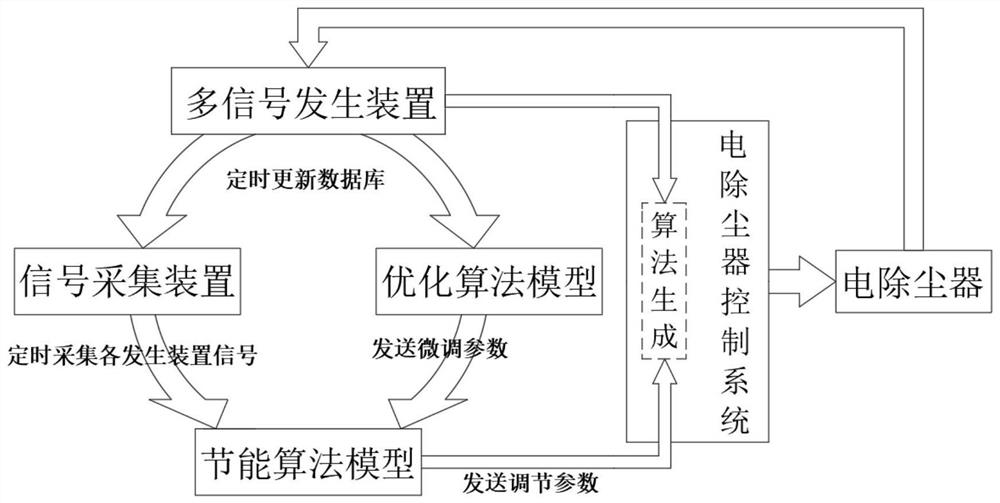
[0040] refer to Figure 1-4 , a multi-signal optimized energy-saving electrostatic precipitator control method, comprising an electric precipitator control system, the electric precipitator control system includes an optimization algorithm system based on the electric precipitator control system, and the optimization algorithm system includes a signal acquisition device, a data storage module and logic analysis module;

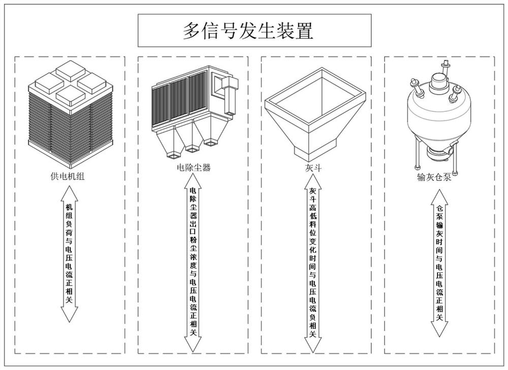
[0041] Signal acquisition device: through different signal collectors corresponding to different signal generation devices, and collect the actual operating status data of different signal generation devices;

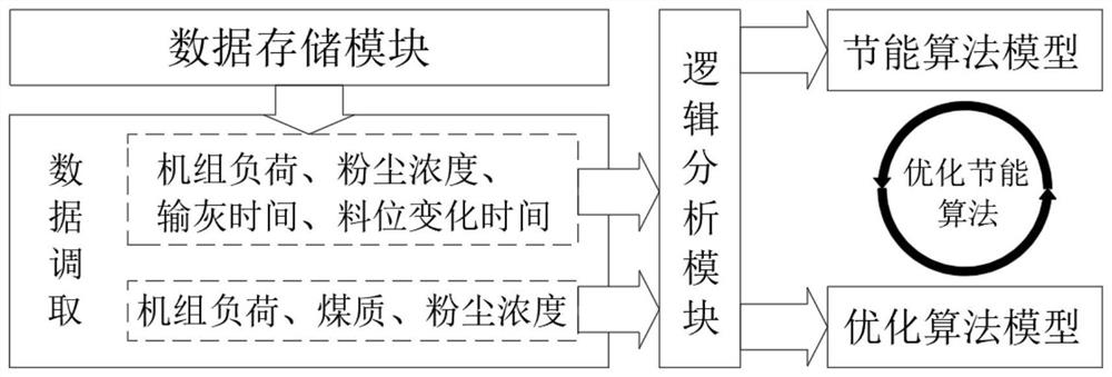
[0042] Data storage module: store the in...


PUM


Abstract

The invention discloses a multi-signal optimization energy-saving electric precipitation control method, and relates to the technical field of energy conservation and environmental protection, the multi-signal optimization energy-saving electric precipitation control method comprises an electric precipitator control system, and the electric precipitator control system comprises an optimization algorithm system based on an electric precipitation control system. The optimization algorithm system comprises a signal acquisition device, a data storage module and a logic analysis module. According to the method, the unit load, the dust concentration of a powder outlet, the dust conveying time of a bin pump and the high-low material level change time of a dust hopper are combined and analyzed to obtain the dust removal efficiency of the electric dust remover with known airflow parameters and dust radiuses under different limit line board intervals, and the optimal dust removal efficiency is found through comparison so as to obtain the optimal operation parameters; and by combining and analyzing unit load, dust concentration of a powder outlet and coal quality parameters and substituting voltage and current when a signal peak value occurs, energy consumption changes of a front system and a rear system are obtained, an optimization strategy of an energy-saving model is obtained, and power consumption of system operation is reduced to the maximum extent.

Description

technical field [0001] The invention relates to the technical field of energy saving and environmental protection, in particular to a multi-signal optimized energy-saving electric dust removal control method. Background technique [0002] Electrostatic precipitator is an essential supporting equipment for thermal power plants. Its function is to remove the particulate smoke and dust in the exhaust gas of coal-fired or oil-fired boilers, thereby greatly reducing the amount of smoke and dust discharged into the atmosphere, which is to improve environmental pollution. , important environmental protection equipment to improve air quality. Its working principle is that when the flue gas passes through the flue in front of the main structure of the electrostatic precipitator, the dust is positively charged, and then the flue gas enters the channel of the electrostatic precipitator with multi-layer cathode plates. Due to the mutual adsorption between the positively charged dust an...

Claims


Application Information

Patent Timeline
Patent Type & Authority Applications(China)
IPC IPC(8): B03C3/68G06F30/20
CPCB03C3/68G06F30/20
Inventor 祁运苓张建军周勇鲍教旗曹敬国张国珍刘同昌程相周白江波
Owner HUANENG QUFU THERMAL POWER CO LTD
Why Eureka
Try Eureka