Industrial waste renewable resource recovery device
A technology of renewable resources and recycling devices, applied in packaging, solid materials, waste treatment, etc., can solve the problems of reducing the purity of steel renewable resources and achieve the effect of improving purity
- Summary
- Abstract
- Description
- Claims
- Application Information
AI Technical Summary
Problems solved by technology
Method used
Image
Examples
Embodiment 1
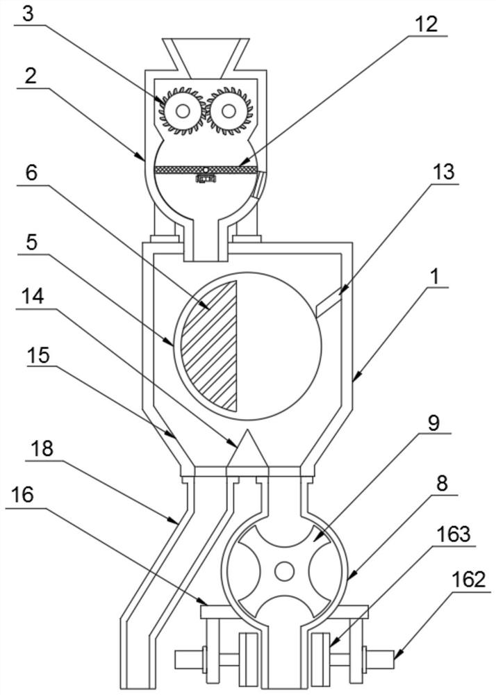
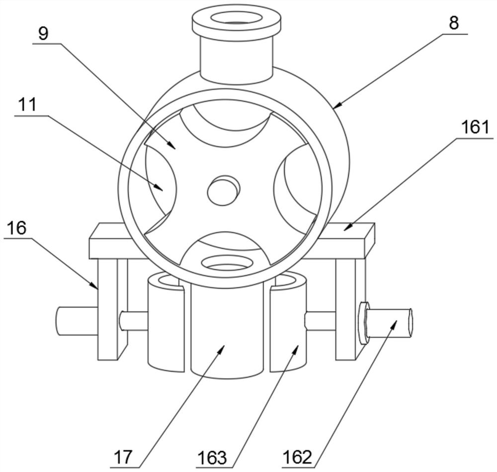
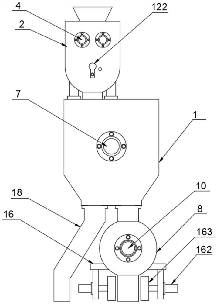
[0026] see figure 1 and image 3 , this embodiment provides an industrial waste recycling resource recovery device, including a magnetic separation chamber 1 and a crushing chamber 2, the upper end of the crushing chamber 2 is welded with a feeding hopper and the caliber of the feeding hopper is in the shape of a large top and a small bottom, the crushing chamber The bottom side of 2 is fixedly connected to the top of the magnetic separation chamber 1 through the connecting column, the bottom feeding pipe of the crushing chamber 2 is plugged into the top feeding port of the magnetic separation chamber 1, and the upper part between the inner walls of the crushing chamber 2 is Two crushing rollers 3 are oppositely arranged, and the upper part of the outer wall of the crushing chamber 2 is fixedly connected to the two crushing rollers 3 with two No. One end of the corresponding crushing roller 3 is fixedly connected, and the end of each crushing roller 3 away from the No. 1 moto...
Embodiment 2
[0030] see Figure 4-5 , further improvements have been made on the basis of Example 1:
[0031] In order to screen out the incompletely broken waste, the inner lower part of the crushing chamber 2 is provided with a disc-shaped groove, and a screening mechanism 12 is arranged in the disc-shaped groove. Screening net 121, the bottom middle part of screening net 121 is equipped with vibrating motor 123;
[0032] In this embodiment, the crushed waste falls onto the screen 121, and at the same time, the vibrating motor 123 vibrates to drive the screen 121 to vibrate, so that the materials are screened more quickly, and the completely crushed materials fall through the screen 121 , and the incompletely crushed materials stay on the screen 121 due to their large particles, so as to prevent the materials with large particles from being stuck in the magnetic separation chamber 1 during magnetic separation.
[0033] In order to discharge the large particle material on the screen 121...
Embodiment 3
[0038] see figure 1 , further improvements have been made on the basis of Example 1:
[0039] In order to carry out magnetic separation better, the slanted lower end of the sloping plate 13 is attached to the outer surface of the magnetic separation cylinder 5, so that the iron and steel particles are completely blocked by the swash plate 13 when performing magnetic separation. When the electromagnet 6 of the magnetic separation cylinder 5 rotates to When away from the side of the iron and steel particles, the iron and steel particles will lose their magnetic adsorption and fall. A triangular prism 14 is arranged below the middle part of the magnetic separation cylinder 5. The bottom surface of the triangular prism 14 is welded to the middle part of the inner wall bottom of the magnetic separation chamber 1. The triangular prism 14 is along the The section in the vertical direction is an isosceles triangle;
[0040] In this embodiment, when the magnetic particles and non-magn...
PUM
 Abstract
Description
Claims
Application Information
 - R&D
- Intellectual Property
- Life Sciences
- Materials
- Tech Scout
- Unparalleled Data Quality
- Higher Quality Content
- 60% Fewer Hallucinations
Browse by: Latest US Patents, China's latest patents, Technical Efficacy Thesaurus, Application Domain, Technology Topic, Popular Technical Reports.
© 2025 PatSnap. All rights reserved.Legal|Privacy policy|Modern Slavery Act Transparency Statement|Sitemap|About US| Contact US: help@patsnap.com


