Method for manufacturing composite glass silicon substrate and adapter plate capable of regulating and controlling large pressure

A composite glass and manufacturing method technology, which is applied in glass manufacturing equipment, manufacturing tools, glass molding, etc., can solve the problem that small-sized reflow glass cannot be processed, substrates and adapter plates take a long time to manufacture, and small spacing cannot be achieved. Problems such as components, to achieve the effect of shortening processing time, reducing equipment requirements, and shortening processing time

Pending Publication Date: 2022-01-28
SOUTHEAST UNIV
View PDF0 Cites 0 Cited by
  • Summary
  • Abstract
  • Description
  • Claims
  • Application Information

AI Technical Summary

Problems solved by technology

[0004] The purpose of the present invention is to provide a method for manufacturing a composite glass-silicon substrate and an adapter plate that can control high pressure, so as to solve the problems in the above-mentioned prior art that cannot be used for the processing of small-sized reflow glass, and cannot realize micro-components with small spacing. The problem of long manufacturing time and low processing efficiency of substrate and adapter board

Method used


Image

  • Method for manufacturing composite glass silicon substrate and adapter plate capable of regulating and controlling large pressure
  • Method for manufacturing composite glass silicon substrate and adapter plate capable of regulating and controlling large pressure
  • Method for manufacturing composite glass silicon substrate and adapter plate capable of regulating and controlling large pressure

Examples


Embodiment 1

[0053] Figure 2- Figure 8 A high-efficiency composite glass-silicon substrate and adapter plate manufacturing technology based on adjustable large pressure is shown, including:

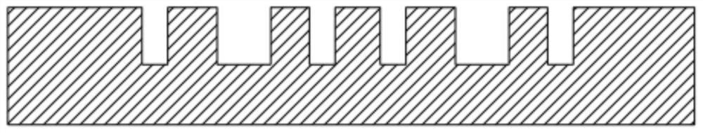
[0054] Step 1, as shown in FIG. 2 , a mold cavity 20 with a micro-component structure 22 is processed on the first substrate wafer 10 . The mold cavity 20 may be processed by deep reactive ion etching (DRIE) or anisotropic wet etching. The processing of the mold cavity 20 can also be performed by combining laser processing with wet etching, dry etching and wet etching, micro-EDM and wet etching, micro-ultrasonic One of the realizations in the method of combining processing and wet etching. The first substrate wafer 10 is a silicon wafer. The thickness of the silicon wafer can be 300um, 500um, 800um, 1mm, 2mm or more, and the diameter of the silicon wafer can be 2 inches, 4 inches, 6 inches, 8 inches, 12 inches. As an example, 6 inches and 1mm thickness are selected. of silicon wafers. The openin...

Embodiment 2

[0061] Figure 2- Figure 8 A high-efficiency composite glass-silicon substrate and adapter plate manufacturing technology based on adjustable large pressure is shown, including:

[0062] Step 1, as shown in FIG. 2 , a mold cavity 20 with a micro-component structure 22 is processed on the first substrate wafer 10 . The mold cavity 20 may be processed by deep reactive ion etching (DRIE) or anisotropic wet etching. The processing of the microstructure mold cavity 20 can also be carried out by combining laser processing with wet etching, combining dry etching with wet etching, combining micro-EDM with wet etching, A realization of the combination of micro-ultrasonic machining and wet etching. The first substrate wafer 10 is a silicon wafer. As an example, an 8-inch 2mm-thick silicon wafer is selected, and an array of mold cavities 20 with openings of 1um, 5um, 10um, and 50um are processed on the silicon wafer. The depth of the mold cavity 20 is about 200um.
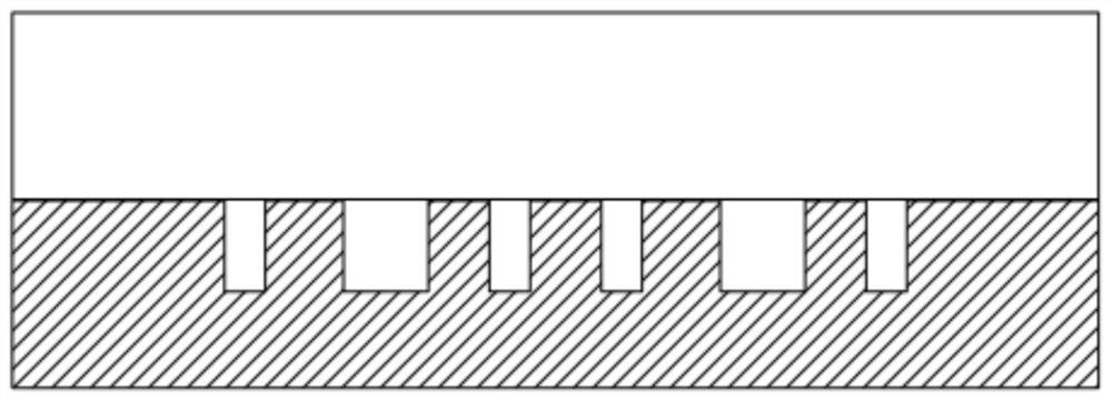
[0063] Step 2, a...


PUM

PropertyMeasurementUnit
softening pointaaaaaaaaaa

Abstract

The invention discloses a method for manufacturing a composite glass silicon substrate and an adapter plate capable of regulating and controlling high pressure. The method comprises the following steps: processing a mold cavity with a micro-component structure on a first substrate wafer; processing a cavity on the second substrate wafer, and adding an outgassing agent into the cavity; bonding the first substrate wafer, the glass wafer and the second substrate wafer with the gas releasing agent in the cavity; heating the three-layer bonded wafer, decomposing the outgassing agent at high temperature to generate gas, and driving the softened glass to flow into a mold cavity by air pressure; preserving heat, and performing cooling and annealing; and performing thinning, grinding and polishing to obtain the composite glass silicon substrate or the adapter plate embedded with the micro component. The method can greatly shorten the processing time and improve the manufacturing efficiency, and is a high-efficiency composite glass silicon substrate and adapter plate manufacturing technology.

Description

technical field [0001] The invention belongs to the field of micro-electro-mechanical systems, and in particular relates to a method for manufacturing a composite glass-silicon substrate and an adapter plate that can regulate high pressure. Background technique [0002] In the field of microelectromechanical system (MEMS) glass processing technology, glass reflow technology was proposed by P.Merz et al. in 2003, and is used to prepare wafer-level microlens arrays. The characteristic of this technology is that the softened glass flows into the vacuum hole or cavity in the silicon wafer by using a pressure difference of one atmosphere to achieve filling or half filling, and can be used to replicate the shape of the hole or cavity. In 2008, J. Liu et al. used glass reflow technology to prepare Pyrex 7740 glass microcavities; in 2011, J. Liu et al. studied the filling degree in glass reflow technology, filling 1.5mm and 2.1mm in softened Pyrex 7740 glass , 2.43mm such a size ho...

Claims


Application Information

Patent Timeline
Patent Type & Authority Applications(China)
IPC IPC(8): B81C1/00C03B23/03C03B23/035
CPCB81C1/00261B81C1/00285B81C1/00325C03B23/03C03B23/035
Inventor 尚金堂罗斌
Owner SOUTHEAST UNIV
Why Eureka
Try Eureka