
Rapid polishing device for transformer bushing and working method of rapid polishing device

A technology of transformer bushing and polishing device, applied in grinding/polishing safety device, grinding drive device, grinding/polishing equipment, etc. Handling and other problems, to achieve the effect of adjustable polishing speed, good environmental protection effect and fast polishing speed

Pending Publication Date: 2022-02-01
江苏金安电气有限公司
View PDF7 Cites 0 Cited by
  • Summary
  • Abstract
  • Description
  • Claims
  • Application Information

AI Technical Summary

Problems solved by technology

Therefore, higher requirements are put forward for the smoothness of the outside of the bushing. At present, when polishing large-scale transformer bushings, the polishing machine can only be used fixedly, which is inconvenient to use, slow in polishing speed, and produces more dust. Real-time processing will affect the sanitation of the working environment, and may also cause dust explosion hazards. In order to solve the above problems, a new rapid polishing device is urgently needed

Method used


Image

  • Rapid polishing device for transformer bushing and working method of rapid polishing device
  • Rapid polishing device for transformer bushing and working method of rapid polishing device

Examples


Embodiment 1

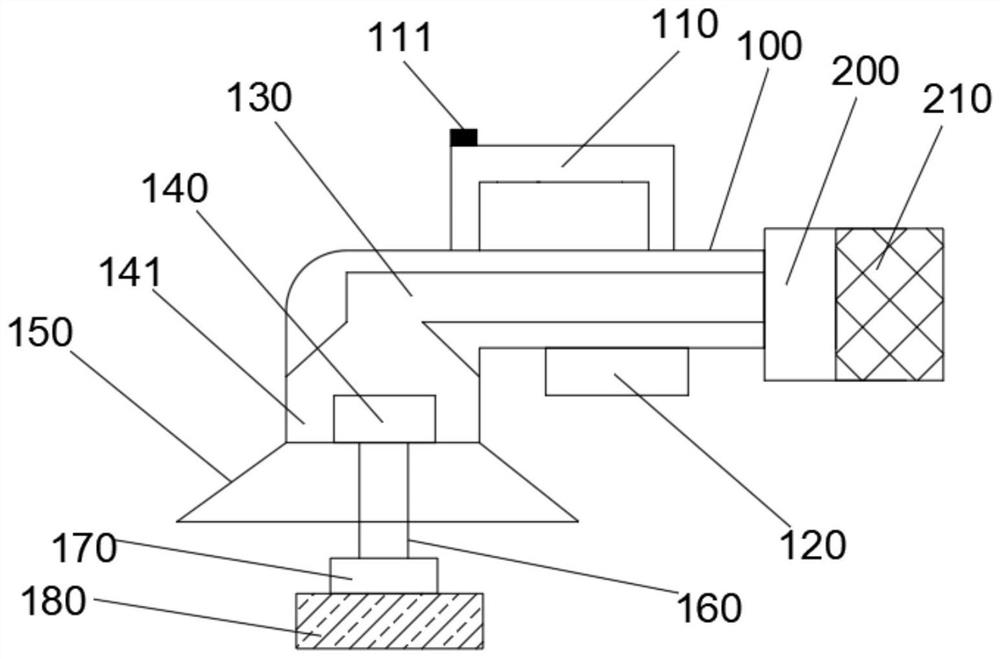
[0022] as attached figure 1 A rapid polishing device for transformer bushings is shown, including an L-shaped device body 100, a handle 110, a two-stage switch 111, a battery compartment 120, an internal air pipe 130, a motor 140, a dust suction channel 141, a dust collection cover 150, Transmission rod 160, polishing rack 170, polishing sheet 180, air pump 200, dust collection box 210; the head of the L-shaped device body 100 is equipped with the dust collection cover 150; the dust collection cover 150 is trumpet-shaped; The L-shaped device body 100 is provided with the handle 110; the handle 110 is provided with a two-stage switch 111; the battery compartment 120 is arranged below the L-shaped device body 100; the L-shaped device The body 100 is provided with the internal air pipe 130; the dust collecting cover 150 is provided with the motor 140; a dust suction channel 141 is left between the motor 140 and the internal air pipe 130; the motor 140 The transmission rod 160 is...

Embodiment 2

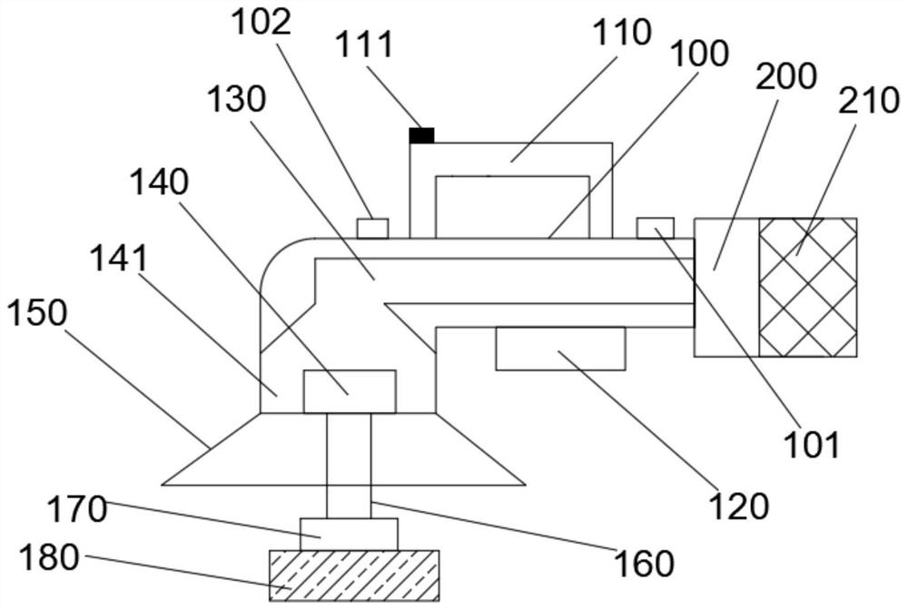
[0026] as attached figure 2 A rapid polishing device for transformer bushings is shown, including an L-shaped device body 100, a handle 110, a two-stage switch 111, a battery compartment 120, an internal air pipe 130, a motor 140, a dust suction channel 141, a dust collection cover 150, Transmission rod 160, polishing rack 170, polishing sheet 180, air pump 200, dust collection box 210; the head of the L-shaped device body 100 is equipped with the dust collection cover 150; the dust collection cover 150 is trumpet-shaped; The L-shaped device body 100 is provided with the handle 110; the handle 110 is provided with a two-stage switch 111; the battery compartment 120 is arranged below the L-shaped device body 100; the L-shaped device The body 100 is provided with the internal air pipe 130; the dust collecting cover 150 is provided with the motor 140; a dust suction channel 141 is left between the motor 140 and the internal air pipe 130; the motor 140 The transmission rod 160 i...


PUM


Abstract

The invention belongs to the field of transformer bushing machining, and particularly discloses a rapid polishing device for a transformer bushing and a working method of the rapid polishing device. The rapid polishing device comprises an L-shaped device body (100), a handle (110), a two-section switch (111), a battery bin (120), an internal air pipe (130), a motor (140), a dust collection channel (141), a dust collection cover (150), a transmission rod (160), a polishing frame (170), a polishing piece (180), an air suction pump (200) and a dust collection box (210). The rapid polishing device is reasonable in design, high in integration degree, good in moving and portability, high in polishing speed, capable of achieving front polishing and side polishing, capable of recycling dust in a polishing process in time and good in environmental protection effect.

Description

technical field [0001] The invention belongs to the field of transformer bushing processing, and specifically discloses a rapid polishing device for transformer bushings and a working method thereof. Background technique [0002] The transformer bushing is the main insulation device outside the transformer box. The lead-out wire of the transformer winding must pass through the insulating bushing to insulate between the lead-out wires and between the lead-out wire and the transformer shell, and at the same time play the role of fixing the lead-out wire. Due to different voltage levels, insulating bushings are available in the form of pure porcelain bushings, oil-filled bushings and capacitor bushings. Pure porcelain bushings are mostly used in transformers of 10kV and below. It is a conductive copper rod inserted in the porcelain bushing, and the inside of the porcelain bushing is air-insulated; oil-filled bushings are mostly used in 35kV transformers. It is filled with oil i...

Claims


Application Information

Patent Timeline
Patent Type & Authority Applications(China)
IPC IPC(8): B24B23/02B24B47/12B24B41/04B24B55/10B24B55/12B24B1/00
CPCB24B23/02B24B47/12B24B41/04B24B55/102B24B55/12B24B1/00
Inventor 安泽庆张艺潇
Owner 江苏金安电气有限公司
Learn More