
Gas well natural gas dehydration treatment device

A processing device and natural gas technology, applied in the direction of wellbore/well components, production fluid, earthwork drilling and production, etc., can solve the problems of reducing the service life of equipment, clogging valves, power consumption, etc., achieve a high degree of automation and reduce the degree of spin , the effect of reducing workload

Inactive Publication Date: 2022-02-08
永春县乾高智能科技有限公司
View PDF0 Cites 0 Cited by
  • Summary
  • Abstract
  • Description
  • Claims
  • Application Information

AI Technical Summary

Problems solved by technology

[0002] The natural gas flowing out from the wellhead of the gas well is almost saturated with gas-phase water, and even carries a certain amount of liquid water. The presence of water in natural gas often causes serious consequences, such as the presence of CO 2 and H 2 S natural gas forms acid in the presence of water to corrode pipelines and equipment; forms natural gas hydrate under certain conditions to block valves, pipelines and equipment; reduces pipeline transportation capacity, causing unnecessary power consumption, and moisture in natural gas The existence of natural gas is very unfavorable, it will reduce the service life of equipment and reduce the production efficiency of gas wells, so natural gas dehydration is very necessary
[0003] Common natural gas dehydration methods include cooling dehydration, absorption dehydration, adsorption dehydration, and dehydration using gas separation membranes. In order to ensure the dehydration effect, the above-mentioned methods are usually used at the same time. Not only are the pipelines complicated and difficult to maintain, but they all have certain shortcomings. For example, absorption and dehydration is easy to introduce solvent impurities into natural gas, and the gas separation membrane also has a certain permeability to water vapor. If based on the existing technology, a new type of natural gas dehydration equipment will be developed to solve the above problems and promote the development of the industry. It will be positive significance

Method used


Image

  • Gas well natural gas dehydration treatment device
  • Gas well natural gas dehydration treatment device

Examples


Embodiment

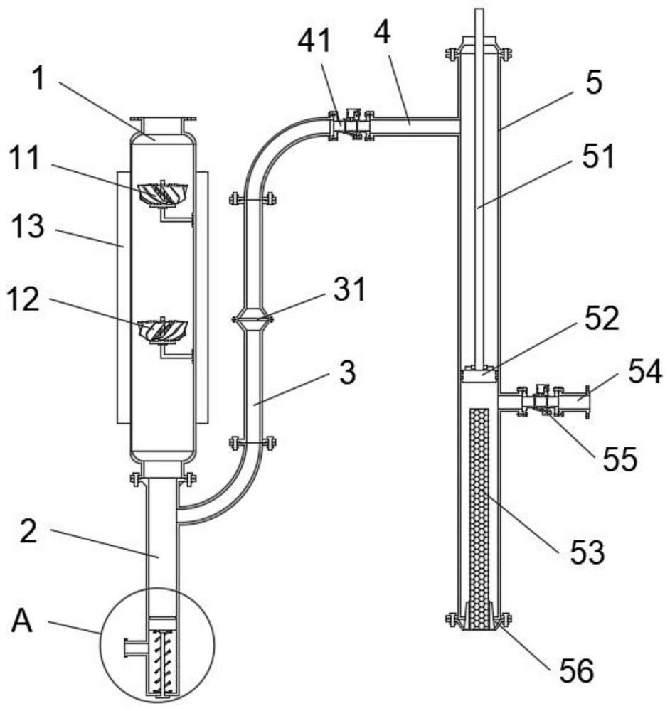
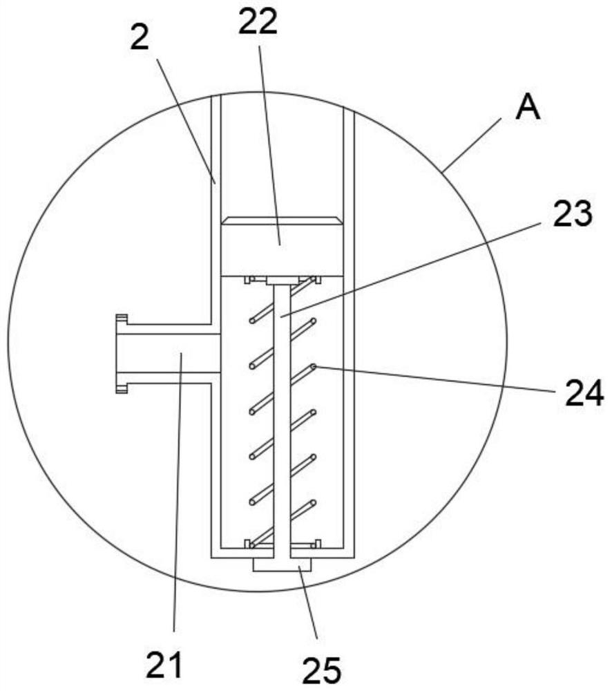
[0025] Combine Figure 1-2 , Including condenser 1, the drain 2, 3 return pipe, the connection pipe 4 and the compression pipe 5, the condenser 1 from the top to bottom with a spin-up means 11 provided helicase apparatus 12, the spin-up means 11 helicase means 12 employed in the particular embodiment the inclined direction of the blade opposite the blade, a condenser side cooling apparatus provided with a guide sleeve 13, the drain pipe 2 to the top condenser and a bottom end communicating, side 2 is provided with drain 2 and the drain discharge port 21 further includes a drain means, both ends of the return pipe 3 as a top arcuate quarter circle with a condenser tube 1 communicates, within the return pipe 3 is provided with a gas separation membrane 31, the said connecting pipe 4 and the two ends of the return pipe 3 to the top, the top of the pipe 5 is connected to the compression, the connection pipe 41 is provided with a first electromagnetic valve 4, the tube 5 includes a comp...


PUM


Abstract

The invention relates to the technical field of natural gas treatment equipment and particularly relates to a gas well natural gas dehydration treatment device. The device comprises a condensation pipe, a drainage pipe, a backflow pipe, a connecting pipe and a compression pipe, wherein liquid drops in natural gas raw materials are rapidly condensed to form primary dehydration through the condensation pipe, and primary separation operation is high in separation efficiency and short in operation time; no chemical reagent is used in the primary separation process, no impurity is introduced, then the natural gas is compressed in the compression pipe after passing through the gas separation membrane, compressed fine liquid drops are condensed and absorbed by the absorption column, then the natural gas is exhausted through the exhaust pipe, the dry natural gas is obtained, the dehydration effect in the process is high, no chemical reagent is used, secondary pollution cannot be caused, the quality of natural gas is improved, normal operation of pipelines and equipment can be ensured, practical significance and popularization value are achieved, and it is expected that good economic benefits can be generated.

Description

Technical field [0001] Technical Field The present invention relates to a gas processing device, in particular to a gas dehydration apparatus wells. Background technique [0002] Gas flows from the wellhead natural gas is almost saturated with water vapor, even carries a certain amount of liquid water, the presence of gas in the water often cause serious consequences, such as those containing CO 2 Hidden 2 S gas is formed in the presence of water and an acid corrosion of piping and equipment; gas hydrates under certain conditions, plug valves, piping and equipment; reduce pipeline capacity, resulting in unnecessary power consumption, gas moisture the very existence is a bad thing, will reduce the life of the equipment, reduce production efficiency gas wells, natural gas dehydration and therefore very necessary. [0003] Common methods include cooling the dehydrated natural gas dehydration, dehydration absorption, adsorption dehydration, and dehydration using a gas separation memb...

Claims


Application Information

Patent Timeline
IPC IPC(8): E21B43/34E21B43/12E21B41/00
CPCE21B43/34E21B43/121E21B41/00
Inventor 陈江友
Owner 永春县乾高智能科技有限公司
Learn More