Fractal butterfly-shaped terahertz antenna

A terahertz and fractal technology, which is applied in the field of terahertz detection and terahertz communication, can solve problems such as energy loss, uneven electric field distribution, and current congestion, and achieve the effects of increased efficiency, simple planar structure, and stable broadband performance

Pending Publication Date: 2022-02-11
SHANGHAI INST OF TECHNICAL PHYSICS - CHINESE ACAD OF SCI
View PDF10 Cites 0 Cited by
  • Summary
  • Abstract
  • Description
  • Claims
  • Application Information

AI Technical Summary

Problems solved by technology

[0006] The antenna structure of the present invention adopts the method of applying the fractal structure to the butterfly antenna, which solves the current problem caused by the single current flow path when the common dish antenna reflects and gathers large-area electromagnetic waves to a smaller semiconductor area. Crowded, uneven distribution of electric field, resulting in a large amount of energy loss

Method used


Image

  • Fractal butterfly-shaped terahertz antenna
  • Fractal butterfly-shaped terahertz antenna
  • Fractal butterfly-shaped terahertz antenna

Examples


Embodiment 1

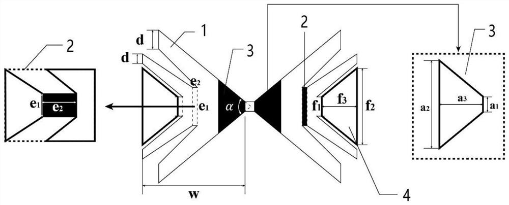
[0025] In the 0.1THz-10THz band range, the fractal butterfly antenna can be self-adjusted according to the size requirements of antennas in different frequency bands to achieve the best antenna coupling efficiency. The scalability of the fractal butterfly antenna enables it to be flexibly applied to multiple frequency bands and reduces the design cost of the antenna.

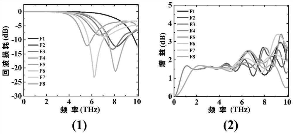
[0026] Aiming at the number of fractal units used, the fractal units were increased from 1 to 8, and the simulation calculations were carried out one by one, and the results were obtained for analysis. in image 3 (1) is a comparison chart of return loss of 8 groups of antennas; (2) is a graph of gain curves corresponding to 8 groups of antennas. As the number of fractal units increases, the resonance point of the antenna is getting closer to the center frequency point. When the fractal unit of the antenna increases to a certain number under a certain range of sizes, the resonance point will start to move away...

Embodiment 2

[0028] in Figure 4 (1) is the reflection loss diagram of the fractal butterfly antenna when the number of fractal units is 3 and 4. When there are 3 pairs of fractal units, the antenna resonates at 6.2-6.3THz and has a return loss of -23.33dB.

[0029] When there are 4 pairs of fractal units, the antenna resonates at 6.2-6.4THz and has a return loss of -13.37dB.

[0030] For the two groups of antennas, the 3-group shaped element and the 4-group shaped element, the return loss data obtained by parameter optimization is compared, for example Figure 4 (2) shown. After parameter optimization, the antenna with three-component shaped elements resonates at a frequency close to the center frequency of 4.9THz, the maximum return loss reaches -33.59dB, and two peaks appear. The antenna of the 4-group shaped element resonates at a frequency close to the center frequency of 5.4THz, and the maximum return loss reaches -34.19dB. There are also two peaks, but the amplitude of the second...

Embodiment 3

[0032] In the present invention, the proposed fractal butterfly antenna adopts two different materials of gold and graphene to simulate and compare. Such as Figure 5 It is the simulation data graph (gain graph, VSWR, S11) of the fractal butterfly antenna using gold and graphene as materials respectively, where graph (1) is a data comparison graph of the antenna gain of two materials; where graph (2) is two The data comparison chart of the VSWR of the material antenna; the figure (3) is the data comparison chart of the return loss of the two material antennas. For the fractal butterfly antenna proposed by the present invention, the simulation results of the graphene material are not much different from the simulation results of gold. The antenna structure proposed by the present invention can weaken the difference in antenna performance caused by materials, and provides more possibilities for material selection of terahertz detectors. The fractal butterfly antenna proposed b...


PUM


Abstract

The invention discloses a fractal butterfly-shaped terahertz antenna. According to the antenna, captured electromagnetic waves are effectively radiated through the antenna arms similar to a fishbone structure, and better coupling light wave energy is achieved. And a conical convergence channel is adopted at the tip part of the antenna, so that the reflection energy of the antenna obtains the opportunity of secondary coupling. According to the structure, the structural characteristics of drainage, shunting and re-convergence are adopted. When the electromagnetic wave initially reaches the surface of the antenna, the first wave energy is led through the trapezoidal antenna tail for the first time; when electromagnetic energy enters the antenna, the electromagnetic energy is shunted through the fishbone channels on the two sides, so that the flow path of current is increased; finally, the energy is converged to a sensitive source through the tip. The antenna is of great significance in improving the detection rate and the target recognition accuracy of the terahertz detector, and the higher working frequency band of the detector in the terahertz field can be improved.

Description

technical field [0001] The present invention relates to the fields of terahertz detection and terahertz communication, and more specifically, relates to an antenna structure applied in the fields of terahertz detection and terahertz communication. Background technique [0002] Terahertz technology is a cutting-edge technology between electronics and photonics. Terahertz waves have many excellent properties, such as low damage, due to the low power level, the ionization effect of terahertz on biological tissues and low waves are not harmful to organisms, making it widely used in the medical field; high spectral resolution, image The resolution increases as the wavelength decreases, and the resolution in the terahertz band is better than that in the microwave region; for visualization, terahertz waves can penetrate non-metallic or non-polar materials due to their shorter wavelengths. Based on the unique characteristics of terahertz waves, and the wide application of terahertz...

Claims


Application Information

Patent Timeline
Patent Type & Authority Applications(China)
IPC IPC(8): H01Q1/36H01Q1/38
CPCH01Q1/36H01Q1/38
Inventor 石艺黄志明邱琴茜马万里李洋李静波高艳卿周炜
Owner SHANGHAI INST OF TECHNICAL PHYSICS - CHINESE ACAD OF SCI
Why Eureka
Try Eureka