Permanent magnet synchronous motor control device and method based on sliding-mode observer and current prediction

A technology of permanent magnet synchronous motor and sliding mode observer, which is applied in the direction of motor generator control, electronically commutated motor control, current controller, etc., and can solve problems such as the inability to overcome the uncertainty of the electronic control system and the difficulty in meeting effective fault tolerance , to achieve the effect of improving dynamic response, improving load capacity, and good speed regulation performance

Pending Publication Date: 2022-02-25
HUNAN UNIV OF SCI & TECH
View PDF0 Cites 0 Cited by
  • Summary
  • Abstract
  • Description
  • Claims
  • Application Information

AI Technical Summary

Problems solved by technology

The PID adjustment method in the traditional vector control has been widely used in the electric drive system due to its simple structure, obvious effect, and easy implementation. The uncertainty caused by the control system makes it difficult to meet the effective fault tolerance under fault conditions

Method used


Image

  • Permanent magnet synchronous motor control device and method based on sliding-mode observer and current prediction
  • Permanent magnet synchronous motor control device and method based on sliding-mode observer and current prediction
  • Permanent magnet synchronous motor control device and method based on sliding-mode observer and current prediction

Examples


Embodiment Construction

[0068] The present invention will be further described below in conjunction with the accompanying drawings and embodiments.

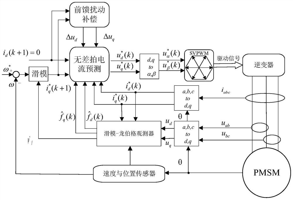
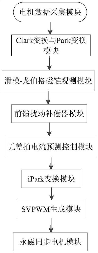
[0069] like Figure 1-Figure 2 As shown, a permanent magnet synchronous motor control device with a sliding mode observer and current prediction, including a PI control module, a Clark transformation module, a Park transformation module, an inverse Park transformation module, a current sensor module, a position sensor module, a disturbance compensation module, Deadbeat current prediction module, SVPWM generation module, permanent magnet synchronous motor module and sliding mode-Lönberg observation module;

[0070] The current sensor module is connected with the Clark transformation module and the permanent magnet synchronous motor module, and is used to collect the stator three-phase current i of the permanent magnet synchronous motor module a i b i c , sending the three-phase current to the Clark transformation module for transformation from the thr...


PUM


Abstract

The invention discloses a permanent magnet synchronous motor control method based on a sliding-mode observer and current prediction. The permanent magnet synchronous motor control method comprises the following steps of collecting the rotating speed and the position angle of a permanent magnet synchronous motor, obtaining the current of the permanent magnet synchronous motor, and obtaining two-phase current and d-axis and q-axis voltages in a rotating coordinate system, establishing a motor feedforward disturbance compensation module to obtain d-axis and q-axis voltage disturbance quantities, establishing a sliding mode-Luenberger observation module to obtain d-axis and q-axis current observation values and a permanent magnet flux linkage equation, establishing a deadbeat current prediction module to obtain d-axis reference voltage and q-axis reference voltage, and acquiring voltage under the two-phase static coordinate system, and generating a switching pulse signal to drive the permanent magnet synchronous motor to operate. According to the method, the dynamic response of the permanent magnet synchronous motor can be improved, the influence on the dynamic performance of the system during nonlinear change of motor parameters is reduced, the real-time flux linkage of the permanent magnet is obtained by adopting the sliding mode-Luenberger state machine, and the robust performance of the speed regulation system during change of the flux linkage of the motor is improved.

Description

technical field [0001] The invention relates to a permanent magnet synchronous motor control device and method for a sliding mode observer and current prediction. Background technique [0002] In recent years, permanent magnet synchronous motors, as the core components of AC speed regulation in electric drive systems, have been widely used in military, aerospace, and industrial industries due to their low power consumption, high power density, wide speed range, and good controllability. Therefore, the highly technology-intensive servo environment also puts forward higher and higher requirements for the accuracy of motor control performance. However, the permanent magnet, the key component inside the motor, is susceptible to complex and changeable operating environments such as humidity, high temperature, and chemical corrosion, and there is an irreversible risk of demagnetization, resulting in serious degradation of motor control performance. In addition, since the permanen...

Claims


Application Information

Patent Timeline
IPC IPC(8): H02P21/00H02P21/13H02P21/22H02P6/28H02P6/34H02P25/026H02P27/08
CPCH02P21/0007H02P21/13H02P21/22H02P6/28H02P6/34H02P25/026H02P27/08H02P2207/05
Inventor 刘朝华夏琦玮廖忠陈磊吕明阳李小花
Owner HUNAN UNIV OF SCI & TECH
Why Eureka
Try Eureka