Positioning device for hydraulic piston cylinder body punching

A technology of hydraulic piston and positioning device, which is applied in positioning devices, manufacturing tools, metal processing machinery parts, etc., can solve the problems of increasing the labor burden of staff and difficult to clean debris, and achieves the effect of reducing burns and improving the collection effect.

Active Publication Date: 2022-03-01
常德市鼎城区正荣机械制造有限公司
View PDF7 Cites 2 Cited by
  • Summary
  • Abstract
  • Description
  • Claims
  • Application Information

AI Technical Summary

Problems solved by technology

[0004] However, when the positioning device in the above-mentioned technology drills the cylinder for positioning and drilling, when the drill bit is drilled from the outside of the cylinder to the inside of the cylinder, a part of debris will be brought into the cylinder, making it difficult for the debris to be effectively removed from the inside of the cylinder. Cleaning up has increased the labor burden of the staff

Method used


Image

  • Positioning device for hydraulic piston cylinder body punching
  • Positioning device for hydraulic piston cylinder body punching
  • Positioning device for hydraulic piston cylinder body punching

Examples


Embodiment 1

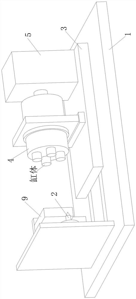
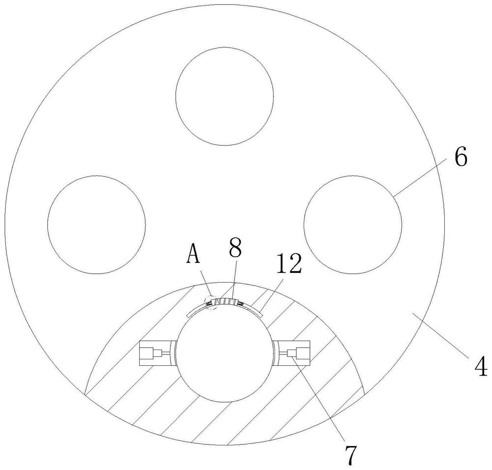
[0032] see Figure 1-Figure 5 As shown, a positioning device for punching a hydraulic piston cylinder according to an embodiment of the present invention includes a support base 1; a drill press 2 is provided on one side of the top surface of the support base 1; The slide table 3 is slidably connected with the drive assembly, and the top of the slide table 3 is connected with the positioning column 4 in rotation, and the side of the slide table 3 away from the drilling machine 2 is provided with a power assembly 5 that drives the positioning column 4 to rotate, and the positioning A group of positioning cavities 6 are provided on the end surface of the column 4 close to the drilling machine 2, and a clamping assembly 7 is arranged inside the positioning cavity 6, and a No. One end of 2 is connected with a blocking plate 9, and the side of the blocking plate 9 close to the positioning column 4 is provided with a negative pressure chamber 10 matched with the cylinder body, and t...

Embodiment 2

[0041] Such as Figure 7 As shown in Comparative Example 1, another embodiment of the present invention is as follows: a set of chute is provided on the side wall where the scraper 20 and the filter screen 15 are attached, and the inside of the chute is slidably connected with a magnetic The sliding block 29 made of material, the elastic member 30 is connected between the sliding block 29 and the inner end of the chute, and the positions corresponding to the filter screen 15 and the chute are inlaid with several groups of ring-shaped and evenly distributed magnetic blocks 31 , the slider 29 can repel it when it moves to the magnetic block 31; when the scraper 20 rotates slowly on the filter screen 15, the slider 29 can slide back and forth in the chute under the action of the magnetic block 31, and The impact on the filter screen 15 promotes the falling of the iron filings adhered to the surface of the filter screen 15, further improving the cleaning effect of the iron filings...


PUM


Abstract

The invention belongs to the technical field of positioning devices, and particularly relates to a positioning device for hydraulic piston cylinder body punching. A drilling machine is arranged on one side of the top face of the supporting seat, a sliding table is slidably connected to the supporting seat, a positioning column is rotatably connected to the top end of the sliding table, a set of positioning cavities are formed in the end face, close to the drilling machine, of the positioning column, clamping assemblies are arranged in the positioning cavities, and first electromagnets are installed at the top ends of the positioning cavities. A plugging plate is connected to the supporting seat, a negative pressure cavity matched with the cylinder body is formed in the side, close to the positioning column, of the plugging plate, and the inner end of the negative pressure cavity is connected with an air pump through an air pipe; according to the punching device, scrap iron in the cylinder body can be effectively sucked out and collected from the punched hole channel position, meanwhile, air flow at the negative pressure cavity can promote dissipation of heat generated by punching of the end of the cylinder body, and the situation that workers are scalded when the machined cylinder body is taken out subsequently is reduced.

Description

technical field [0001] The invention belongs to the technical field of positioning devices, in particular to a positioning device for drilling holes in hydraulic piston cylinders. Background technique [0002] Now the small hydraulic cylinder body is mainly processed by a drilling machine, and the drill bit of the drilling machine is used to drill the cylinder body to be processed, thus forming a cylinder body, but when the current drilling device is drilling the cylinder body, The workpiece is positioned and clamped mainly through the positioning fixture device, and then the workpiece is drilled with a drilling machine. [0003] A Chinese patent with a publication number of 209318842U discloses a new type of drilling device for a hydraulic piston cylinder, including a horizontal drilling machine and a tooling fixture. It can disassemble and clamp other processed cylinders, so that the drilling machine does not need to stop when it is working, which speeds up the maximum ef...

Claims


Application Information

Patent Timeline
Patent Type & Authority Applications(China)
IPC IPC(8): B23Q3/06B23Q3/18B23Q11/00B23Q11/10
CPCB23Q3/062B23Q3/183B23Q11/0046B23Q11/0064B23Q11/10B23Q11/00
Inventor 陈广周强唐金代亚烽
Owner 常德市鼎城区正荣机械制造有限公司
Why Eureka
Try Eureka